Industrial / Door Controls
User Manual for BEA 300 MHz Wireless Transmitters & Receivers
Quick guide for installing and configuring the BEA 300 MHz wireless system. Includes wiring diagrams, DIP switch access code settings, and mounting instructions for the 10RD300 receiver and compatible transmitters.
Table of contents
Manual images
Click an image to enlargeQuick guide from the manual
This document provides installation and configuration instructions for the BEA 300 MHz wireless family, including the 10RD300 receiver and various compatible transmitters. Before beginning, ensure all power to the door header is shut off. Installers should maintain a clean, safe environment and ensure compliance with all applicable safety standards, such as ANSI A156.10.
Mounting & Wiring Receiver
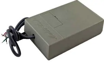
The 10RD300 receiver can be mounted outside the header or concealed inside. If mounting inside the header, you must drill a 1/8 inch hole in the top of the header and route the antenna through the hole to improve the receiver's detection range.
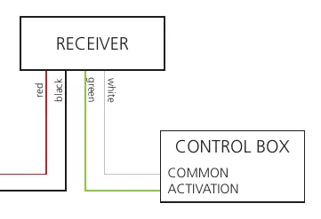
Wiring connections:
- Red/Black wires: Connect to 24 VAC / VDC power.
- Green/White wires: Connect to the Control Box Common and Activation terminals.
Always check the placement of all wiring before powering up to ensure that moving door parts will not catch any wires.
Mounting & Wiring Transmitter
Transmitters require a battery (3V, 9V, or 12V depending on the model). Insert the battery mounting clip into the designated slot.
Mounting steps:
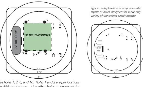
- Use the designated holes in the push plate box for mounting the transmitter circuit board.
- Use holes 1, 2, 6, and 10. Holes 1 and 2 are pin locations for BEA transmitters.
- You must use at least 3 pins for secure mounting.
Setting Access Code
The system uses 10 DIP switches to set the access code. The settings on both the receiver and the transmitter must match exactly to allow signal reception.
- Use a ballpoint pen or similar object to press the switches.
- Press the switch toward the number to set it to the ON position.
- Dual Transmitters: If using multiple sets, each receiver/transmitter pair must be set to a different code to avoid signal confusion.
Technical Specifications
- Frequency: 300 MHz
- Radio Control Type: Analog
- Input Voltage: 24 VAC / VDC
- Operating Temperature: 14 – 131 °F
- Set-up: 10 DIP switch access code programming
- Norm Conformance: CE, FCC, IC
Manufacturer information
BEA Sensors
Practical help
Common problems
Signal not received
Ensure DIP switch settings on both the receiver and the transmitter match exactly.
Signal confusion with multiple units
Each receiver and transmitter set must be configured to a unique access code.
Poor detection range
If the receiver is mounted inside the header, drill a 1/8 inch hole and route the antenna through it.
Before use
- Shut off all power to the header before attempting any wiring.
- Verify the correct battery type for your specific transmitter model (3V, 9V, or 12V).
- Ensure the work area is clean and safe.
- Check that all wiring is clear of moving door parts to prevent damage.
- Verify that all appropriate industry signage and warning labels are in place.
Specs in practice
- Input Voltage
- Requires 24 VAC or 24 VDC power supply.
- Operating Temperature
- Device functions within 14 to 131 °F.
Images and diagrams
- Wiring Diagram: Shows the red and black wires for 24V power and green and white wires for activation.
- DIP Switch: 10-switch block; press switches toward the number to set the code.
Model compatibility
- Compatible transmitters include: 10T300HH, 10T300HHDBL, 10T300HH4, 10T300KEYCHAIN, 10T300PB, and 10T300MINIPB.

Manual page author
Emily Carter
User documentation editor
Prepares concise manual descriptions and highlights the most useful setup, operation, and maintenance information for readers.