Industrial / Door Controls
User Manual for BEA Ultimo Sliding Door Sensor
Comprehensive user guide for the BEA Ultimo sliding door sensor. Includes installation, wiring diagrams, programming instructions, radar and infrared field setup, and troubleshooting steps.
Table of contents
Manual images
Click an image to enlargeQuick guide from the manual
The BEA Ultimo is an activation and safety sensor designed for automatic sliding doors. It utilizes microwave doppler radar for motion detection and active infrared (AIR) for presence detection. Installation and setup should only be performed by trained and qualified personnel. The sensor can be configured using the onboard LCD screen or a remote control. Always test the system for proper operation according to ANSI 156.10 standards before leaving the site.
Product description
The sensor consists of several key components:
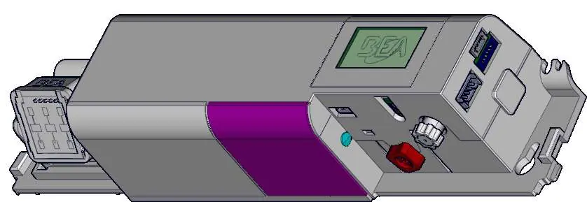
- Cover: Protective housing for the sensor electronics.
- Radar antenna: Detects motion.
- AIR receiver and emitter: Used for presence detection.
- LCD screen: Interface for configuration and diagnostics.
- Adjustment knobs: Used for setting the AIR curtain angle and main adjustments.
- Main connector: Interface for power and signal wiring.
Installation and wiring
Mount the sensor centered over the clear opening, ensuring the bottom of the sensor is no higher than 5 inches from the bottom of the door header. Secure the sensor to avoid vibrations. Route the harness using the provided wire stay.
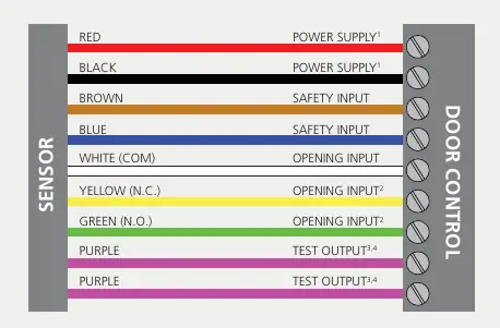
Wiring connections:
- Red/Black: Power supply (12-24 VAC or 12-30 VDC).
- Brown/Blue: Safety input.
- White: Opening input (COM).
- Yellow/Green: Opening input (N.C./N.O.).
- Purple: Test output.
Ensure the door control unit and header cover profile are correctly grounded.
Programming and setup
The sensor can be programmed via the LCD menu or a remote control. To use the LCD, push the button to enter the menu, enter the password if necessary, and navigate using the scroll and select functions. Always lock the sensor after completing adjustments. The sensor supports factory resets (full or partial) to restore settings.
Radar field adjustments
The radar detection field can be adjusted for angle and shape:

- Angle: Tilt the antenna up to adjust depth outward and down to adjust inward.
- Shape: Use the LCD menu or remote control to select between wide or narrow lobes.
Active infrared safety field
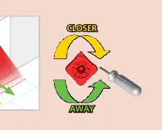
The AIR safety field uses curtains to detect presence. You can choose the number and position of curtains based on the application. Use the red adjustment knob to position the curtains correctly. The sensor features ULTI-SYNC to eliminate crosstalk when multiple sensors are installed near each other.
Troubleshooting
The sensor uses LED signals to indicate status and errors:
- Red LED: Indicates motion or presence detection. Flashing red may indicate setup errors or password protection.
- Orange LED: Indicates internal faults, power supply issues, or communication errors.
- Green LED: Indicates motion detection or environmental disturbances.
If the sensor does not react, check the power supply and wiring. For specific error codes (E1-E8), refer to the troubleshooting section in the manual for corrective actions.
Manufacturer information
BEA Sensors
Practical help
Common problems
Red LED flashes quickly after setup
The sensor sees the door during setup. Move the AIR curtains away from the door and launch a new assisted setup.
Door cycles open and remains open
Check if the door control monitoring is set to Active High or if the safety output is set incorrectly.
Sensor vibrates
Ensure the sensor is secure, and header cover screws and mounting screws are tight.
No power to sensor
Check wiring and verify the power supply voltage is within the 12-24 VAC or 12-30 VDC range.
Before use
- Ensure mounting height is between 6'6" and 11'6".
- Verify the door control unit and header cover are correctly grounded.
- Check that the infrared field is clear of obstructions.
- Ensure the sensor is mounted securely to avoid vibrations.
- Verify wiring connections against the provided diagram.
- Test for proper operation according to ANSI 156.10.
Specs in practice
- Mounting height
- 6'6" – 11'6" (typical 7'2").
- Supply voltage
- 12 – 24 VAC or 12 – 30 VDC.
- Degree of protection
- IP54 (dust and splash resistant).
- Radar frequency
- 24.150 GHz.
Images and diagrams
- Wiring diagram shows color-coded connections for power, safety input, opening input, and test output.
- Component diagram identifies the radar antenna, AIR receiver/emitter, and adjustment knobs.
Model compatibility
- Compatible with automatic sliding doors.
- Requires trained personnel for installation.
- Do not exceed 26.4 VAC power supply.

Manual page author
David Miller
Documentation analyst
Organizes user manual content into clear summaries, with attention to model details, product context, and everyday usability.