Industrial / Door Controls
Installation Guide for BEA 10PS-RR Magic Switch Restroom Kit
Complete installation and configuration guide for the BEA 10PS-RR Magic Switch Restroom Kit. Includes wiring diagrams, logic module setup, actuator programming, and troubleshooting steps.
Table of contents
Manual images
Click an image to enlargeQuick guide from the manual
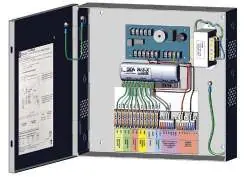
The BEA 10PS-RR Magic Switch Restroom Kit is designed for touchless restroom access. The system includes a power supply cabinet with a logic module, a door position switch, and MS42 actuators. Key installation steps involve mounting the cabinet, wiring the door position switch and electric strike, and configuring the logic module (BR3-X) for the specific restroom application (normally locked or normally unlocked). Actuators require specific DIP switch settings and potentiometer adjustments to function correctly.
Safety Precautions
- Shut off all power to the header before performing any wiring.
- Ensure the door control system and header cover are correctly grounded.
- Use ESD precautions when handling circuit boards.
- Do not use harsh cleaning agents (e.g., ammonia) on polycarbonate surfaces; use clean, lukewarm water and a soft cloth.
- Perform a tug test on all wire terminations to ensure secure connections.
Installation
Cabinet Mounting: Run site power and device cabling through the appropriate knockouts. Mark mounting holes, drill pilot holes, insert anchors, and fasten the cabinet securely to the wall.
Door Position Switch: Mount the switch as close as possible to the leading edge of the door frame. Adhere the magnet to the door, ensuring it is fully attached. Strip wires and connect to the power supply cabinet.
Electric Strike: Mount and wire the electric strike according to the manufacturer's instructions, then connect to the power supply cabinet.
Actuators: Determine mounting locations, ensuring interior actuators are at least 12 inches apart to avoid radar interference. Install mounting boxes and apply silicone to drilled holes to maintain IP65 rating. Wire actuators to the power supply cabinet.
Logic Module Configuration
The BR3-X logic module must be programmed for the restroom application:
- nL (Normally Locked): Exterior actuator unlocks strike and opens door; interior actuator unlocks strike and opens door; interior lock actuator deactivates exterior wave-to-open.
- nU (Normally Unlocked): Exterior actuator opens door; interior actuator opens door; interior lock actuator deactivates exterior wave-to-open and locks strike.
How to change settings: Press and hold INCR + FUNC for 3 seconds. Use INCR to cycle through functions (FF/00) and FUNC to cycle through parameters. Set hold times (h1, h2) and delay times (d1) as required.
Actuator Programming
Remove the actuator faceplate to access DIP switches and the potentiometer. Settings for restroom applications:
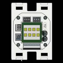
- Output Mode: Both DIP switches OFF for pulse/N.O.
- Buzzer: DIP 3 OFF for no buzzer, ON for buzzer upon detection.
- LED Color: All DIP switches OFF for green (no detection) and red (detection).
- Range: Adjust potentiometer clockwise to increase range (max 23 inches).
Troubleshooting
- Door does not open/lock: Check power supply, detection range, wiring, and ensure the door position switch is making contact when the door is closed.
- Sensor stays in detection: Remove moving objects from the sensor area and check wiring.
- BR3-X not reacting: Ensure the unit is programmed (not displaying 00) and that all 'h' values are set to at least 01.
- BR3-X has no output: Verify wiring and jumper settings.
Technical Specifications
Power Supply: 115VAC, 60Hz, 0.6A input; 12VDC or 24VDC selectable output.
Logic Module: 12-24 VAC/VDC supply voltage; relay contact ratings 3A @ 24VAC/30VDC.
Door Position Switch: 0.43" gap distance; N.C. reed form.
Actuator: 24.150 GHz microwave motion sensor; IP55 rating (IP65 with silicone).
Manufacturer information
BEA Sensors
Practical help
Common problems
Door does not open or lock upon hand wave
Check power supply, adjust detection range, verify wiring/relay connections, and ensure the door position switch is making contact when the door is closed.
Sensor stays in detection
Remove any moving objects around the sensor and check wiring/relay connections.
BR3-X will not react to any inputs
Verify 12-24 VAC/VDC power, ensure the unit is programmed (not displaying 00), and verify 'h' values are set to at least 01.
BR3-X output is constant/maintained
Resolve short circuits on inputs IN-1 through IN-4.
Before use
- Shut off all power to the header before wiring.
- Ensure the door control system is correctly grounded.
- Verify DIP switches are set to OFF before installing actuators.
- Ensure interior actuators are spaced at least 12 inches apart.
- Perform a tug test on all wire terminations.
- Apply silicone to drilled holes for IP65 rating.
Specs in practice
- Detection range
- 4 to 24 inches (adjustable via potentiometer).
- Output hold time
- 0.5 seconds in pulse mode.
Images and diagrams
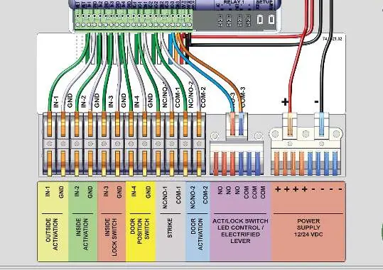
- The wiring diagram on page 5 details terminal connections for Outside Activation, Inside Activation, Inside Lock Switch, Door Position Switch, Strike, Door Activation, and Power Supply.
Model compatibility
- A store room function lever is recommended for a fully touchless system.

Manual page author
Emily Carter
User documentation editor
Prepares concise manual descriptions and highlights the most useful setup, operation, and maintenance information for readers.