Industrial / Door Controls
User Manual for BEA Magic Switch MS21H Activation Sensor
Quick guide for the BEA Magic Switch MS21H touchless activation sensor. Includes installation steps, wiring diagrams, sensor adjustment settings, and troubleshooting tips.
Table of contents
Manual images
Click an image to enlargeQuick Guide
The BEA Magic Switch MS21H is a touchless activation sensor designed for automatic doors. Key requirements for successful operation include the use of a BEA-provided isolation module for each sensor and proper grounding. Upon powering, the device requires approximately 10 seconds to complete its initialization sequence. Always test the sensor operation before leaving the installation site.
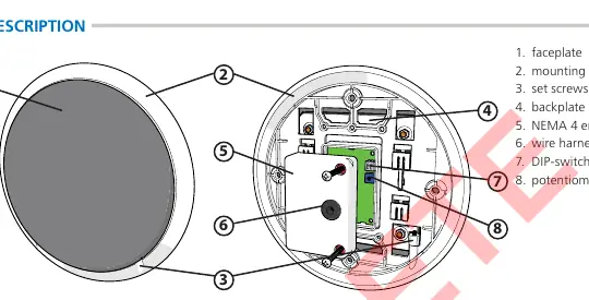
Product Description and Specifications
The MS21H uses capacitive sensing technology to detect proximity. It is housed in a NEMA 4 enclosure, making it suitable for various environments.
- Technology: Capacitive sensing
- Detection Mode: Proximity
- Supply Voltage: 12 – 24 VAC/VDC
- Sensing Zone: 0 – 4 inches (adjustable)
- Relay: 1-Form A Solid State Relay (0.4A 60 VAC/VDC max)
- Temperature Range: -20 to 120 degrees Fahrenheit
Installation
The sensor is compatible with single or double gang electrical boxes. Follow these steps for installation:

- Install the electrical box.
- Remove the two set screws and disassemble the faceplate assembly from the mounting ring.
- Temporarily mount the mounting ring to the electrical box, ensuring the "THIS END UP" orientation is correct.
- Mark the four hole locations, remove the ring, and install wall anchors.
- Mount the ring to the electrical box and wall.
- Remove the back of the NEMA 4 enclosure.
- Complete wiring and settings before final assembly.
- Reassemble the faceplate to the mounting ring and secure with the two set screws.
Wiring
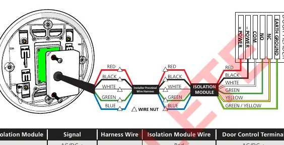
Important: You must use a BEA-provided isolation module for each MS21H. The red wire must connect to power (+) and the black wire to power (-).
- Use 300 V, low-voltage shielded cabling.
- Maintain a distance of at least 6 inches from power lines of 120 VAC/VDC or higher.
- If using a wire harness with more than 5 conductors, wire all extra conductors to Earth Ground at both ends.
- Connect the isolation module to the door control using the provided wiring chart.
Settings and Adjustments
Adjustments are made on the sensor board:
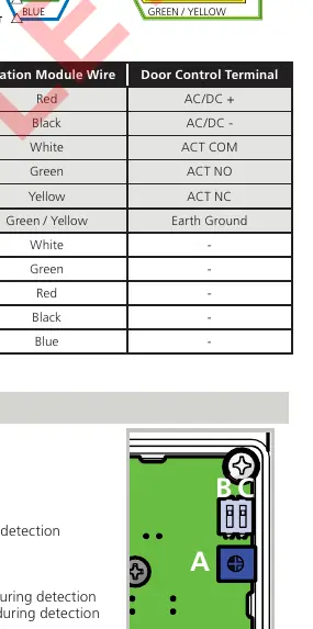
- Sensing Zone (Potentiometer): Turn counterclockwise to decrease (0 inch minimum) or clockwise to increase (4 inch maximum).
- Audible Alert (DIP-switch 1): Set to ON for a 0.5-second pulse during detection; OFF to disable.
- LED (DIP-switch 2): Set to ON for LED on at rest (pulses off during detection); OFF for LED off at rest (pulses on during detection).
Functionality
- Activation: Signal is held until the sensing zone is cleared.
- Rejection: Objects must be in the zone for at least 130 milliseconds to trigger detection.
- Tracking: The sensor learns baseline capacitance to ignore stationary objects (e.g., chewing gum on the faceplate) after 5 seconds.
Troubleshooting
If the sensor is erratically detecting or falsely activating, ensure it is properly grounded and that the BEA isolation module is being used. If the sensor is not detecting, verify the power supply and increase the sensing zone via the potentiometer. For further assistance, contact BEA technical support at 1-800-523-2462 or visit www.beainc.com.
Official resources from the manual
Manufacturer information
BEA Sensors
Practical help
Common problems
Sensor erratically detecting or falsely activating
Verify continuity between sensor ground and earth ground; ensure BEA isolation module is used; reduce sensing zone.
Sensor not detecting
Increase sensing zone (potentiometer clockwise); verify power supply and connections.
Electrical noise interference
Reduce sensing zone (potentiometer counterclockwise) and ensure no non-stationary objects are within the detection zone.
Before use
- Ensure installation is performed by trained and qualified personnel.
- Verify the use of a BEA-provided isolation module.
- Check that the electrical box is compatible (single or double gang).
- Confirm power supply is 12-24 VAC/VDC.
- Test operation before leaving the premises.
Specs in practice
- Sensing Zone
- The detection range (0-4 inches), adjustable based on object size and speed.
- 1-Form A Relay
- Solid state relay type used for switching the door control signal.
Images and diagrams
- The wiring diagram illustrates the connection between the sensor, the isolation module, and the door header.
- The settings diagram identifies the potentiometer (A) and DIP-switches (B, C) on the sensor board.
Model compatibility
- Requires BEA-provided isolation module for each sensor.
- Compatible with single or double gang electrical boxes.
- Not for use within the swing path of the door.

Manual page author
David Miller
Documentation analyst
Organizes user manual content into clear summaries, with attention to model details, product context, and everyday usability.