Lighting / Fixtures
User Manual for BEGA 23256.4K3 Wall Luminaire
Quick guide for the BEGA 23256.4K3 indoor wall luminaire. Includes installation instructions, technical specifications, maintenance procedures, and safety guidelines.
Quick answers from the manual
Quick answer
- The BEGA 23256.4K3 is an indoor wall luminaire. Installation requires a qualified electrician, 350 mm clearance for maintenance, and 460 mm mounting hole spacing. p. 1, 2
Key actions
- Install the luminaire p. 2
- Replace LED module p. 3
Problems and fixes
Thermal shutdown
The luminaire has a BEGA Thermal Switch to protect components; ensure ambient temperature is below 45°C.
p. 1, 2Show 3 more answers Show less
Maintenance and reset
- LED module replacement p. 3
Technical specifications
| Parameter | Value | Meaning | Pages |
|---|---|---|---|
| Luminaire connected wattage | 15.5 W | Total power consumption of the luminaire. | p. 2 |
| Voltage | 220-240 V, 0/50-60 Hz | Operating voltage range. | p. 1, 2 |
| Protection Class | I | Requires earth connection. | p. 1 |
| IP Rating | IP44 | Protection against solid objects ≥ 1 mm and splash water. | p. 1 |
| Ambient temperature | max 45°C | Maximum operating temperature. | p. 2 |
Where to find it in the PDF
- Product Overview and Safety p. 1
- Installation and Technical Data p. 2
- Maintenance and Spare Parts p. 3
Table of contents
Manual images
Click an image to enlargeQuick guide from the manual
The BEGA 23256.4K3 is an indoor wall luminaire featuring hand-blown opal glass and a metal housing. It is designed for interior lighting tasks requiring soft and uniform light distribution. Installation and commissioning must be performed by a qualified electrician in accordance with national safety regulations.
Product Description
The luminaire is constructed from aluminum with a velvet brass finish. It features an insulating housing for the electrical connection and is rated IP44 (protected against granular foreign bodies ≥ 1 mm and splash water) and IK02 (impact strength). It includes a BEGA Thermal Switch for temporary thermal shutdown to protect temperature-sensitive components.
Installation
Important: A minimum distance of 350 mm must be maintained between the removable cap and the wall for mounting and dismantling.
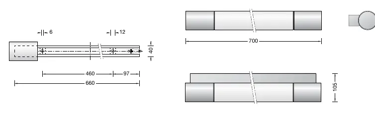
- Preparation: Drill mounting holes into the mounting surface with a spacing of 460 mm.
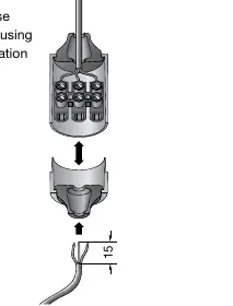
- Electrical Connection: Open the insulation housing. Strip the mains supply cable (max 15 mm) and lead it through the cable entry (max diameter 10.5 mm).
- Wiring: Make the earth conductor connection and electrical connection. Ensure the outer coating of the cable is fully enclosed by the compression nipple.
- Assembly: Connect both parts of the insulation housing until they audibly engage. Fix the luminaire to the mounting surface using suitable material.
- Finishing: Place the glass into the luminaire housing, close with the cap, and screw in the knob.
Maintenance
The LED module can be replaced by qualified persons using standard tools. Always disconnect the system from the power supply before maintenance. To access the module, loosen the lateral knob, remove the cap, and take out the glass. If the glass is defective, it must be replaced.
Technical Data
The luminaire is available in two color temperatures (3000K and 4000K). It operates on 220-240 V, 0/50-60 Hz (DC 176-280 V). The luminaire connected wattage is 15.5 W.
Manufacturer information
BEGA
Practical help
Common problems
Luminaire does not turn on
Ensure the system is connected to power and the electrical connection in the insulation housing is secure.
Thermal shutdown
The luminaire features a BEGA Thermal Switch. If it shuts down, it is protecting temperature-sensitive components; ensure ambient temperature does not exceed 45°C.
Glass or LED module damage
Defective glass must be replaced. LED modules can be replaced by qualified personnel using standard tools.
Before use
- Ensure installation is performed by a qualified electrician.
- Maintain a minimum clearance of 350 mm from the wall for the removable cap.
- Drill mounting holes with 460 mm spacing.
- Ensure mains supply cable diameter is max 10.5 mm.
- Ensure the outer cable coating is fully enclosed by the compression nipple.
- Verify the power supply is 220-240 V, 0/50-60 Hz.
Show more Show less
Specs in practice
- Safety Class I
- Requires earth conductor connection.
- Ambient temperature (ta max)
- Maximum operating temperature is 45°C.
Images and diagrams
- The dimension diagram shows the 460 mm mounting hole spacing and the 350 mm clearance requirement.
- The insulation housing diagram illustrates the cable entry and connection points.
Model compatibility
- Indoor use only.
- Requires qualified electrician for installation.
- Compatible with standard tools for LED module replacement.

Manual page author
Emily Carter
User documentation editor