Electronics / Networking
User Manual for Black Box PoE Media Converter LPS602A-MM850 / LPS603A-SM1310
Quick guide for the Black Box PoE Media Converter. Learn how to install, configure DIP switches, understand LED indicators, and check technical specifications for models LPS602A-MM850 and LPS603A-SM1310.
Table of contents
Quick Guide from the Manual
The Black Box PoE Media Converter is designed to connect fiber to copper networks while providing power to PoE devices. It features auto-sensing bandwidth (10/100/1000Mbps) and includes a PSE controller to output power via CAT twisted-pair cables. The device includes a Powered Device (PD) reset capability, where a fiber link breakdown can disable PSE power output for approximately 2 seconds to allow the connected device to reset.
Overview and Installation
Before installation, ensure you have the correct fiber cable type (multi-mode or single-mode) as specified by your part number. Follow these steps to install the unit:
- Connect Fiber: Attach a fiber cable from the converter to the fiber network. Ensure the fiber connections are matched: connect the transmit socket to the receive socket.
- Connect Network: Attach a UTP cable from the TP network device to the RJ-45 port on the converter.
- Power Up: Plug in the power supply to power the unit. Verify that the power LED lights up.
- Verify Connection: The TP Act and FX Act LEDs will light up when all cable connections are satisfactory.
LED Indicators
The front panel provides visual status updates:
- FXAct: Lit when the FX connection is good; blinks when FX data is transmitting.
- Power: Lit when the unit is powered on.
- PSE: Lit when PoE is actively working.
- Link/Act: Lit when the TP connection is good; blinks when TP data is transmitting.
DIP Switch Settings
The converter includes DIP switches for communication settings:
- SW1: On to enable Link Fault Pass-Through; Off to disable.
- SW2: On for Cut-Through (9K); Off for Store and Forward.
- SW3: On to enable Flow control; Off to disable.
- SW4: On for FX Speed 100Mbps; Off for 1000Mbps.
Technical Specifications
Key technical parameters for the converter:
- Connector Type: SC fiber connector, RJ-45 UTP.
- Fiber Cable: Supports various single-mode and multi-mode specifications.
- TP Cable: Cat5 UTP cable (max length 100 meters).
- Operating Temperature: 32 to 122°F (0 to 50°C).
- Dimensions: 1" H x 2.8" W x 3.7" D (25.4 x 71.5 x 99 mm).
- Warranty: Lifetime.
Regulatory Information
This equipment complies with FCC Class B regulations for commercial environments. It is also RoHS compliant. Ensure the device is installed in accordance with the provided instructions to avoid radio interference.
Practical help
Common problems
Fiber link failure
Ensure fiber connections are matched correctly (transmit socket to receive socket).
Device not powering up
Verify the power supply is securely connected to the AC input jack and the power outlet.
No network activity
Check that both TP Act and FX Act LEDs are lit, indicating satisfactory cable connections.
Before use
- Verify the fiber cable type (multi-mode or single-mode) matches your specific model.
- Ensure you are using a Cat5 UTP cable for the network connection.
- Confirm the power supply is connected to an appropriate AC source.
- Check that the fiber transmit and receive sockets are correctly matched.
Specs in practice
- Link Fault Pass-Through
- A feature that allows the converter to pass link fault status between fiber and copper ports.
Images and diagrams
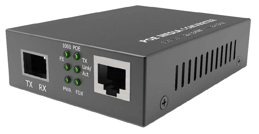
- The front panel contains the RJ-45 port, the fiber port (TX/RX), and status LEDs for 1000, PoE, FX, TX, Link/Act, Power, and FDX.
Model compatibility
- Fiber connections must be matched: transmit socket to receive socket.
- Maximum length for Cat5 UTP cable is 100 meters (330 ft).
- The converter is auto-sensing between 10, 100, and 1000mbps.

Manual page author
Emily Carter
User documentation editor
Prepares concise manual descriptions and highlights the most useful setup, operation, and maintenance information for readers.