HVAC / Parts & Accessories
Service Manual for Bosch IDS Heat Pump 115V Modular Blower
Service manual for the Bosch IDS Heat Pump 115V Modular Blower. Includes detailed troubleshooting charts, LED error code diagnostics, control module DIP switch settings, wiring diagrams, and fan motor check procedures.
Table of contents
Manual images
Click an image to enlargeQuick Guide and Safety
This service manual is intended for qualified service agents. Before performing any maintenance, ensure the power is disconnected. Always discharge your body's static electricity before touching the integrated control module to prevent damage. When handling sheet metal parts, wear appropriate protective clothing, safety glasses, and gloves to avoid injury from sharp edges.
Troubleshooting
The unit uses diagnostic LED blinks to indicate specific operational problems. Refer to the troubleshooting chart to identify the issue based on the LED status:
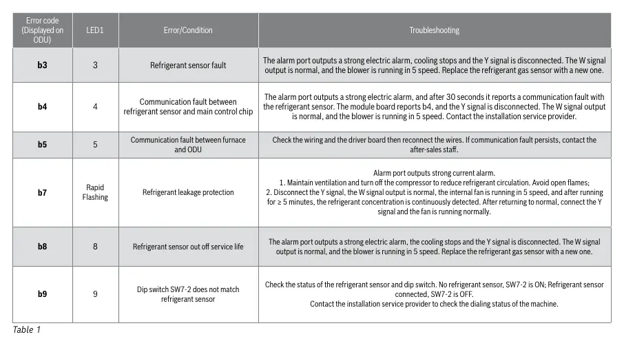
- b3 (3 blinks): Refrigerant sensor fault. Replace the refrigerant gas sensor.
- b4 (4 blinks): Communication fault between refrigerant sensor and main control chip. Contact installation service provider.
- b5 (5 blinks): Communication fault between furnace and ODU. Check wiring and driver board.
- b7 (Rapid Flashing): Refrigerant leakage protection. Turn off the compressor, maintain ventilation, and avoid open flames.
- b8 (8 blinks): Refrigerant sensor out of service life. Replace the sensor.
- b9 (9 blinks): Dip switch SW7-2 does not match refrigerant sensor. Check switch settings.
Control Module Settings
The control module features DIP switches for configuring fan speed and communication modes. Ensure settings are correct for your specific installation:
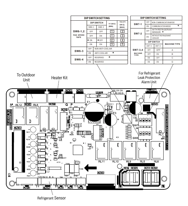
- SW6-1, SW6-2: Configure fan speed taps.
- SW6-3: Anti-cool air settings.
- SW7-1: Communication mode (Non-communication vs. Communication).
- SW7-2: Refrigerant sensor configuration (With vs. Without sensor).
- SW7-3, SW7-4: Machine type selection (A, B, C, or D).
Wiring Diagram
The wiring diagram provides a reference for electrical connections, including the terminal block, transformer, fan motor, and control board. Ensure all wiring is properly polarized and grounded according to N.E.C. and local codes. Use copper conductors only, and if replacing wires, ensure they have a temperature rating of at least 105 degrees Celsius.
Fan Motor Check
If the fan does not start normally, perform the following voltage checks:
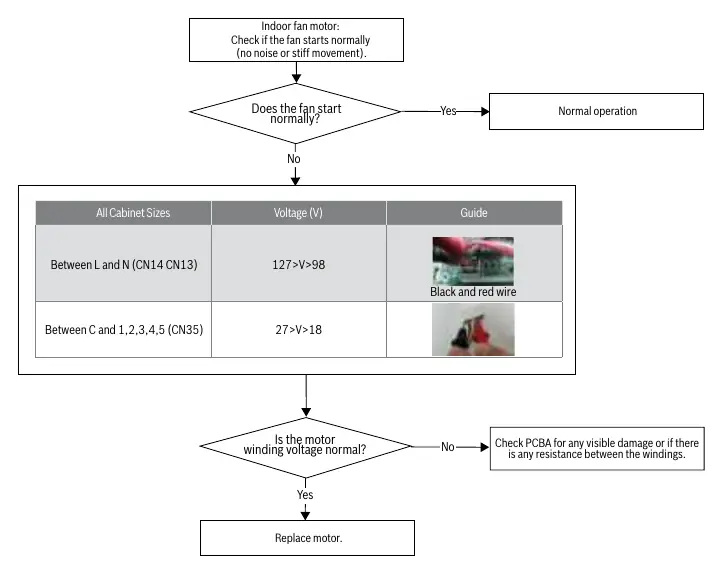
- Between L and N (CN14, CN13): Voltage should be between 98V and 127V.
- Between C and 1, 2, 3, 4, 5 (CN35): Voltage should be between 18V and 27V.
If the motor winding voltage is normal but the fan does not start, check the PCBA for visible damage or resistance between windings. If the issue persists, replace the motor.
Manufacturer information
Bosch
Practical help
Common problems
Refrigerant sensor fault (b3)
Replace the refrigerant gas sensor.
Communication fault (b4/b5)
Check wiring and driver board connections; reconnect if necessary.
Refrigerant leakage protection (b7)
Turn off compressor, maintain ventilation, avoid open flames, and disconnect Y signal.
Dip switch mismatch (b9)
Check SW7-2 setting (OFF for sensor connected, ON for no sensor).
Before use
- Ensure power is disconnected before servicing.
- Discharge body static electricity before touching the control module.
- Verify wiring polarization and grounding.
- Check for refrigerant leaks if indicated by LED codes.
- Ensure replacement wires are rated for at least 105 degrees Celsius.
Specs in practice
- Fan Motor Voltage (L-N)
- Normal range is 98V to 127V.
- Fan Motor Voltage (C-1,2,3,4,5)
- Normal range is 18V to 27V.
Images and diagrams
- Wiring Diagram: Shows connections for power supply, transformer, fan motor, and control board.
- Control Module: Details DIP switch settings for fan speed and communication modes.
- Troubleshooting Flowcharts: Visual guides for diagnosing LED flash codes.
Model compatibility
- Compatible with Bosch R-454B IDS Products.

Manual page author
Michael Turner
Technical manual editor
Reviews PDF manuals for structure, safety notes, and practical product details so readers can find the right information quickly.