HVAC / Ventilation Systems
Installation Guide for Vallox 125 MV Ceiling Mounting Plate
A comprehensive installation guide for the Vallox 125 MV ceiling mounting plate. Includes step-by-step mounting instructions, locking mechanism details, clearance requirements, and duct connection diagrams.
Table of contents
Manual images
Click an image to enlargeQuick Installation Guide
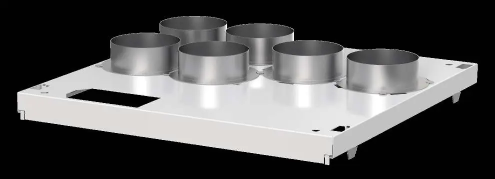
The Vallox 125 MV ceiling mounting plate is designed to securely hold the ventilation unit to the ceiling structure. Key installation requirements include ensuring the M8 thread bars are level, maintaining a 500 mm distance for the service door to access cables, and correctly using the operating levers (A) to lock the unit in place.
Installation Steps
- Fasten the M8 thread bars to the rafter frames or ceiling structure and attach the nuts (1).
- Lift the ceiling mounting plate into position.
- Install a rubber damper (3) and a washer (2) onto each thread bar.
- Adjust the nuts to ensure the mounting plate is perfectly level. Ensure the thread bar ends are no more than 5 mm below the fastening nut.
- Verify that the condensate insulation rings are correctly placed in the outlet collars below the plate.
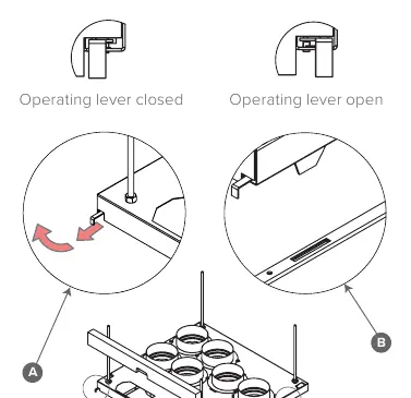
- Pull the operating levers (A) out and lock them by turning them toward the outer sides of the unit.
- Remove the unit door before installation.
- Lift the ventilation unit to the plate, feeding cables and the connection box through the designated hole.
- Lift the unit against the plate and release the levers (A) by turning them toward the center to lock the unit. If necessary, guide the mounting hooks (B) into the grooves on the unit's side panels.
Important Installation Notes
- Service Door: You must create a service door in the ceiling approximately 500 mm from the mounting plate to allow access to cables and the connection box.
- Thread Bar Security: Ensure there are nuts (1) above the mounting plate to prevent it from lifting during unit installation. Tighten the upper nut adequately.
- Mounting Options: The plate can be installed flush against the ceiling or recessed (up to 30 mm below the upper edge).
- Unit Removal: To detach the unit, remove the door, lift the unit slightly, pull out both operating levers (A), and lock them.
Dimensions and Duct Outlets
The manual provides specific duct outlet configurations for models 125A through 125H. Refer to the diagrams to identify the correct supply, extract, exhaust, and outdoor air connections for your specific unit model.
Clearance Requirements
Ensure adequate space is provided for installation:
- Water seal: 75 mm installation space.
- Elbow: 47 mm installation space.
- Side wall: Recommended 10 mm distance from the finished side wall.
- Rear wall: 10 mm distance from the finished rear wall.
Practical help
Common problems
Unit does not lock into place
Ensure the operating levers (A) are pulled out and turned toward the center. Check that the mounting hooks (B) are aligned with the grooves on the unit's side panels.
Mounting plate is not level
Adjust the nuts on the M8 thread bars until the plate is level.
Cannot access cables or connection box
Ensure a service door was installed in the ceiling approximately 500 mm from the mounting plate.
Before use
- Ensure M8 thread bars are securely fastened to the frame.
- Verify condensate insulation rings are in place in the outlet collars.
- Check that the service door is planned for cable access.
- Ensure thread bar ends are no more than 5 mm below the fastening nut.
- Verify that the unit door is removed before attempting to mount the unit.
Specs in practice
- M8 Thread bar
- Required for mounting the plate to the ceiling structure.
- Operating levers (A)
- Used to lock and unlock the ventilation unit to the mounting plate.
- Service door distance
- Approximately 500 mm from the mounting plate is required for maintenance access.
Images and diagrams
- Operating levers (A): Shown in closed and open positions for locking the unit.
- Duct outlets: Diagrams show specific configurations for models 125A through 125H.
Model compatibility
- Designed for Vallox 125 MV ventilation units.
- Supports both surface and concealed mounting (up to 30 mm recessed).

Manual page author
Michael Turner
Technical manual editor
Reviews PDF manuals for structure, safety notes, and practical product details so readers can find the right information quickly.