Power / Solar Systems
Lumena Charleston Brick Light 12V
Quick guide for installing and maintaining the Lumena Charleston Brick Light 12V. Includes wiring instructions, mounting steps, technical specifications, and maintenance tips for outdoor use.
Table of contents
Manual images
Click an image to enlargeQuick guide from the manual
The Lumena Charleston Brick Light 12V is a low-voltage outdoor lighting fixture. Key requirements for installation include a 12V transformer (sold separately) and parallel wiring. The unit is rated IP65, making it suitable for outdoor environments. Always ensure the power is switched off at the mains before performing any installation or maintenance work.

Safety Warnings
- This is a Class 3 product (Low Voltage) and does not require an earth connection.
- A 12V transformer is required and must be purchased separately.
- Install in accordance with IEE Wiring Regulations and Building Regulations.
- The light fitting should be connected to a circuit with a 30mA RCD fitted.
- All electrical connections must be made as watertight as possible to prevent electrical shortages.
- 12V lighting must be wired in parallel, not in series.
- Keep cable lengths to a minimum to prevent voltage drop.
Technical Specifications
- Voltage: 12V Low Voltage
- Max Wattage: 50W
- Bulb Holder: G4 x 2 (lamps sold separately)
- IP Rating: IP65
- Cable Length: 1.5m
- Cable Type: 0.75mm 2 Core (H05RN-F)
- Cable Inlets: Back Centre
- Mounting Box Dimensions: Approx. (L)210 x (H)56 x (D)65mm
Installation
Before permanent installation, it is recommended to test the fittings and bulbs. Ensure there is sufficient room for the fitting, cable, and any junction boxes or transformers.
Brick Wall Mounting
- Build the brass mounting box directly into the brick wall. The box must protrude by approximately 2-3mm to allow for the faceplate overlap and a waterproof seal.
- If the brick size differs, a wooden frame can be used to support the fitting.
- Install 2 x G4 lamps.
- Replace the front plate and secure it with the 2 brass screws, ensuring the rubber washers and foam seal are correctly positioned. Do not overtighten.
Recess into Flat Surface
- Cut out the hole for the mounting box in the masonry or decking.
- Hold the brass mounting box in position and mark the 2 screw holes on either side.
- Remove the box. For masonry, drill and install wall plugs; for wood, pilot holes may be drilled.
- Secure the mounting box in place with relevant screws.
- Install 2 x G9 lamps.
- Replace the front plate and secure it with the 2 brass screws, ensuring the foam seal is in place.
Wiring and Connection
Important: A 240V to 12V transformer is required (sold separately).
- Connect the fitting to the transformer or extension cable using a waterproof junction box or connector.
- Ensure all terminals on the connector block are secure with no stray wires and that the connection is watertight.
- Connect the transformer to the mains supply. The 240V input cable must be located inside an armoured conduit.
- Once fully installed, turn on the mains power.
Maintenance and Cleaning
Occasional cleaning is recommended. If condensation occurs due to temperature differences, turn off the power, remove the front plate, and wipe the inside dry with a soft cloth. A silica gel pouch can be placed inside the fitting to absorb excess moisture.
Practical help
Common problems
Condensation inside the fitting
Turn off power, remove front plate, wipe dry with a soft cloth. Consider placing a silica gel pouch inside.
Voltage drop over long cable runs
Keep cable runs as short as possible and use thicker cable (1.5mm or 2.5mm) for longer distances.
Transformer overheating
Ensure the transformer has adequate air circulation.
Before use
- Purchase a 12V transformer (sold separately).
- Ensure the circuit has a 30mA RCD fitted.
- Verify that the power supply is switched off at the mains.
- Check that you have the correct G4 bulbs.
- Ensure all connections are watertight.
Specs in practice
- 12V Low Voltage
- Requires a 12V transformer; no earth connection required.
- Parallel Wiring
- All lights connect directly to the transformer output, not daisy-chained.
Images and diagrams
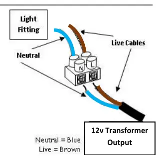
- Wiring diagram shows the light fitting connecting to the 12V transformer output.
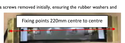
- Mounting box includes side brackets and cable protrusion, with fixing points 220mm centre to centre.
Model compatibility
- Must be wired in parallel, not series.
- Requires 12V transformer (sold separately).
- 240V input cable must be located inside armoured conduit.

Manual page author
Michael Turner
Technical manual editor
Reviews PDF manuals for structure, safety notes, and practical product details so readers can find the right information quickly.