Automotive / Lighting Accessories
User Manual for Cell2 160607M53 Lighthead
Quick guide for the Cell2 160607M53 lighthead. Learn how to install using adhesive or bezel mounts, wire the unit, synchronize multiple heads, and configure flash patterns.
Table of contents
Quick guide from the manual
The Cell2 160607M53 is a vehicle lighthead designed for warning applications. This manual covers two installation methods: adhesive foam mounting and bezel mounting. It also details wiring requirements, synchronization of multiple units, and flash pattern configuration.
Installation
Adhesive Foam Mount
- Remove the existing corner, head, or tail light from the vehicle.
- Select the mounting location on the light assembly.
- Drill a 1-inch diameter cut-out on the light assembly.
- Clean the surface thoroughly with alcohol.
- Insert the lighthead through the double-sided adhesive foam and the cut-out.
- Press firmly for 1 minute.
- Apply silicone (user-supplied) for a better seal. Warning: Do not cover the heatsink with silicone, as this may damage the product and void the warranty.
Bezel Mount
- Use the mounting foam to mark wire and screw holes before drilling.
- Carefully drill the marked holes.
- Insert lighthead wires through the mounting foam and into the wire hole.
- Secure the lighthead using the supplied sheet metal screws.
- Mount the snap-on bezel onto the lighthead.
Wiring and Operations
Wiring Connections
- Red Wire: Connect to +VDC (requires a 2A fuse).
- Black Wire: Connect to Chassis Ground.
- Yellow Wire: Used for synchronization, grouping, and changing flash patterns.
Synchronization and Grouping
To synchronize multiple heads, connect the YELLOW wires of all heads together. All heads must be set to the same flash pattern.
To set Simultaneous or Alternating Flash:
- Apply +VDC to RED and YELLOW wires simultaneously to enter Grouping mode. The lighthead will display short flashes: Single flash = Group 1; Double flash = Group 2.
- Remove the YELLOW wire from +VDC and momentarily apply it to +VDC to change groups.
- Disconnect power to save and exit Grouping mode.
Flash Patterns
To change flash patterns, momentarily apply +VDC to the YELLOW wire:
- Once for the next pattern.
- Quickly three times to reset to FP#1.
Available patterns include: 1. Random, 2. Steady, 3. Single, 4. Mega, 5. Double, 6. Triple, 7. Quad, 8. Quint, 9. Ultra, 10. Single-Quad, 11. Single H/L, 12. Single-Triple-Quint.
Maintenance and Removal
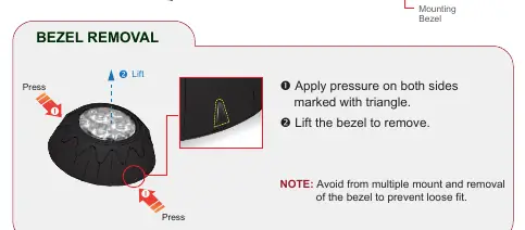
To remove the bezel, apply pressure on both sides marked with a triangle and lift. Avoid multiple mount and removal cycles to prevent a loose fit.
Manufacturer information
Cell2
Practical help
Common problems
Lighthead not flashing correctly
Ensure all connected lightheads are set to the same flash pattern.
Bezel becomes loose
Avoid frequent mounting and removal of the bezel.
Warranty voided
Do not cover the heatsink with silicone during installation.
Before use
- Clean the mounting surface thoroughly with alcohol.
- Ensure the power source is fused at 2A.
- Verify that the mounting location is suitable for the light assembly design.
- Ensure the heatsink remains uncovered.
Images and diagrams
- The wiring diagram illustrates the connection of Red to +VDC, Black to Ground, and Yellow for synchronization.
- The bezel removal diagram shows pressing on the triangle-marked sides to release the bezel.
Model compatibility
- Mounting location may vary depending on the design of the vehicle light assembly.
- Sheet metal screws are not applicable when mounting with double-sided adhesive foam.

Manual page author
Emily Carter
User documentation editor
Prepares concise manual descriptions and highlights the most useful setup, operation, and maintenance information for readers.