Automotive / Lighting Accessories
Installation and Operation Manual for Cell2 Serial-bus Controller
Quick guide for the Cell2 Serial-bus Controller. Includes installation steps, wiring diagrams, LED status indicators, and firmware programming instructions.
Quick answers from the manual
Quick answer
- The Cell2 Serial-bus Controller is installed by mounting it in a protected area, wiring the 18-pin and 6-pin harnesses according to the diagram, and using the USB-C port with PC software for programming and firmware updates. p. 1, 2
Key actions
- Connect the 6-PIN harness to the controller and Lightbar CAN wires. p. 1
- Upload firmware by flipping the Mode Switch to Upload Mode. p. 2
First start
- Test fit all cables, drill mounting holes using the template, secure the unit, and connect wiring. p. 1
Problems and fixes
CAN Bus Error
Reboot and check Lightbar power and connection.
p. 1Where to find it in the PDF
- Installation and Wiring p. 1
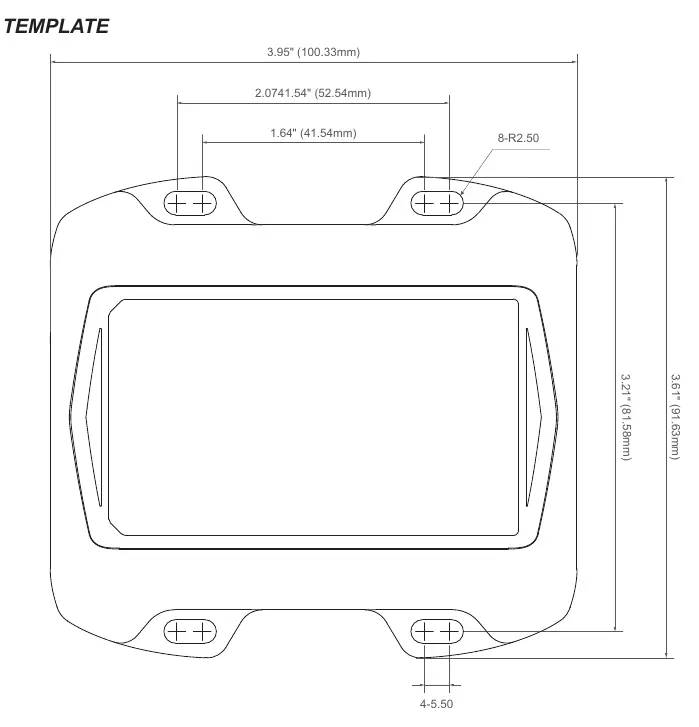
- Programming and Drilling Template p. 2
Table of contents
Quick guide from the manual
This document provides instructions for the installation, wiring, and firmware programming of the Cell2 Serial-bus Controller. Proper installation requires knowledge of automotive electronics. Ensure all cables are test-fitted before final mounting.
Installation
Follow these steps to install the controller:
- Select a location not exposed to weather elements (e.g., driver compartment firewall, below the seat, or in the trunk).
- Ensure the location does not interfere with airbag deployment.
- Use the provided drilling template to mark and drill mounting holes.
- Secure the controller using the provided self-drilling screws.
- Connect the harness and wires according to the wiring diagram.
Wiring and Connections
The controller features several ports and connectors:
- RJ45 Port: Not used.
- 18-PIN (I/O): Plug the 18-pin harness here. Connect individual I/O wires based on specific function requirements.
- 6-PIN (Power / Lightbar CAN): Plug the 6-pin harness here. Connect the two Serial-bus signal and SHIELD wires to the Lightbar CAN cable. Connect the RED wire to an ignition-controlled circuit (must accommodate 250mA load). Connect the two BLACK wires to the chassis ground.
- USB Type-C Port: Used for PC programming via a user-supplied cable.
Programming and Firmware Upload
To customize lightbar functions:
- Flip the Mode Switch to PC Mode and connect the controller to a PC via a Type-C cable.
- Use the GUI software to load the configuration onto the controller.
- Plug the 6-pin harness into the controller and connect the CANBus signal/SHIELD wires to the lightbar.
- Power up the controller and lightbar.
- Flip the Mode Switch to Upload Mode to start the firmware upload.
- Once the status LED displays flashing green, flip the switch back to Normal / PC Mode.
Status LED Indicators
The status LED provides feedback on system operation:
- Normal / PC Mode: Green (Steady) indicates normal system operation. Red (Steady) indicates a CAN Bus error; reboot and check connections.
- Upload Mode: Green (Flashing) indicates upload complete. Red (Slow Flashing) indicates uploading in progress. Red (Fast Flashing) indicates a data error; reload the configuration file. Red (Steady) indicates upload failure; retry the process.
Manufacturer information
Cell2
Practical help
Common problems
CAN Bus Error (Red Steady LED in Normal Mode)
Reboot the system and check the Lightbar power and connection.
Data Error (Red Fast Flashing LED in Upload Mode)
Reload the configuration file from the PC via the GUI software.
Upload Failed (Red Steady LED in Upload Mode)
Retry the upload steps starting from Step 5.
Before use
- Ensure the installer has a good understanding of automotive electronics.
- Test fit all cables and harnesses before proceeding with installation.
- Ensure the mounting location is not exposed to weather elements.
- Verify the ignition-controlled circuit can accommodate an additional 250mA load.
- Ensure the correct USB Type-C cable is available for programming.
Specs in practice
- 18-PIN Harness
- Used for I/O connections; specific wire functions depend on the purchased model.
- 6-PIN Harness
- Used for Power and Lightbar CAN connection.
- USB Type-C Port
- Interface for PC programming and configuration.
Images and diagrams
- The wiring diagram details the pinout for the 18-pin and 6-pin connectors.
- The drilling template provides precise dimensions for mounting the controller.
Model compatibility
- Exact function for each wire is based on the specific model purchased.
- Requires specialized PC software for programming.

Manual page author
Emily Carter
User documentation editor
Prepares concise manual descriptions and highlights the most useful setup, operation, and maintenance information for readers.