Automotive / Car Audio
User Manual for Cerwin-Vega Vega Series Subwoofers
Quick guide for Cerwin-Vega Vega Series subwoofers. Includes wiring configurations, impedance selector instructions, enclosure recommendations, and technical specifications for V8, V10, V12, V15, and V65 models.
Quick answers from the manual
Quick answer
- The Vega Series subwoofers feature an integrated impedance selector. You can adjust the impedance by pulling and rotating the terminal. Wiring configurations (series or parallel) determine the final ohm load (1Ω, 2Ω, 4Ω, or 8Ω) presented to the amplifier. p. 4, 5
Key actions
- Adjusting Impedance p. 4
- Wiring Subwoofer p. 5
Technical specifications
| Parameter | Value | Meaning | Pages |
|---|---|---|---|
| Power Handling (Nom/Max) | 500W/1500W to 1500W/4500W | Varies by model (V65 to V15) | p. 4 |
Where to find it in the PDF
- Introduction p. 2
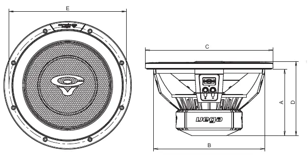
- Features and Dimensions p. 3
- Specifications p. 4
- Wiring Configuration p. 5
- Enclosures p. 6
- Warranty p. 7
Table of contents
Manual images
Click an image to enlargeQuick Guide from the Manual
The Cerwin-Vega Vega Series subwoofers are designed for high-output bass performance. This manual covers the installation, wiring, and enclosure requirements for the V8, V10, V12, V15, and V65 models. Key features include an integrated impedance selector and high-excursion capabilities.
Integrated Impedance Selector
To simplify installation, these subwoofers feature a single terminal impedance selector. To adjust the impedance:
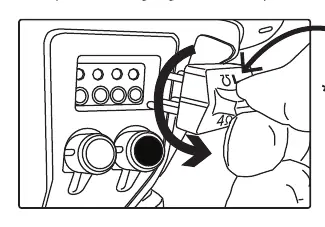
- Pull out the terminal.
- Rotate it to the desired impedance setting.
- Ensure the amplifier is rated for the resulting ohm load.
Wiring Configuration
The subwoofers feature dual 2Ω or 4Ω voice coils. Both coils must be connected to the amplification source. The final load depends on the wiring method:
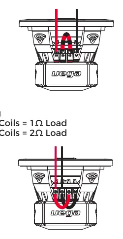
- Series Wiring: Increases the ohm load (e.g., Dual 2Ω coils = 4Ω load; Dual 4Ω coils = 8Ω load).
- Parallel Wiring: Decreases the ohm load (e.g., Dual 2Ω coils = 1Ω load; Dual 4Ω coils = 2Ω load).
Enclosure Recommendations
The manual provides specific volume and dimension requirements for both sealed and ported enclosures for each model size (V65, V8, V10, V12, V15). Always ensure the enclosure is built to the recommended specifications to maintain sound quality and prevent damage.
Technical Specifications
The manual includes detailed Thiele/Small parameters for all models, including SPL, Re, Qms, Qes, Qts, Fs, Vas, Cms, Mms, Sd, BL, Xmax, and Power Handling (Nominal/Max). Refer to the specifications table in the manual for the exact values corresponding to your specific model (e.g., V15DV2 vs V15DV4).
Warranty
Cerwin-Vega provides a one-year warranty from the date of purchase for defects in material and workmanship, provided the product was purchased from an authorized retailer in the United States. The warranty does not cover damage caused by burnt voice coils, negligence, improper use, abuse, or unauthorized repairs.
Practical help
Common problems
Impedance mismatch
Ensure the amplifier is stable at the final ohm load (1Ω, 2Ω, 4Ω, or 8Ω) created by your wiring configuration.
Burnt voice coils
This is not covered under warranty. Ensure the amplifier power does not exceed the subwoofer's handling capabilities and avoid clipping.
Before use
- Verify the subwoofer model (e.g., V8DV2 vs V8DV4) to understand its voice coil configuration.
- Determine the required enclosure type (sealed or ported) based on the model.
- Ensure the amplifier is compatible with the final impedance load after wiring.
- Use appropriate gauge speaker wire for the installation.
Specs in practice
- Mounting Depth
- The minimum depth required inside the enclosure for the subwoofer magnet structure.
- Cut out Diameter
- The diameter of the hole required in the enclosure baffle to mount the subwoofer.
Images and diagrams
- The impedance selector diagram shows how to pull and rotate the terminal to set the desired impedance.
- Wiring diagrams illustrate how to connect dual voice coils in series or parallel to achieve the target ohm load.
Model compatibility
- Subwoofers are available in dual 2Ω or 4Ω voice coil configurations.
- Requires an amplifier capable of handling the specific final impedance load.

Manual page author
David Miller
Documentation analyst
Organizes user manual content into clear summaries, with attention to model details, product context, and everyday usability.