Automotive / Car Audio
Installation Guide for Morel Maximus 602 V2 Component Speakers
Installation and setup guide for the Morel Maximus 602 V2 2-Way Component Speaker system. Includes mounting instructions for tweeters and woofers, crossover wiring diagrams, and technical specifications.
Quick answers from the manual
Quick answer
- The Morel Maximus 602 V2 is a 2-way component speaker system. Installation involves wiring the crossover to the amplifier and speakers, and mounting the tweeters via flush or surface methods. p. 1, 3, 4
Key actions
- Flush mount the tweeter p. 4
- Connect the crossover p. 3
Technical specifications
| Parameter | Value | Meaning | Pages |
|---|---|---|---|
| Nominal Impedance | 4 ohm | Speaker resistance | p. 4 |
| Power Handling | 90W | Continuous power rating | p. 4 |
| Frequency Response | 60-22,000 Hz | Range of sound reproduction | p. 4 |
Where to find it in the PDF
- Parts and Woofer Mounting p. 2
- Crossover and Tweeter Surface Mounting p. 3
- Flush Mounting and Specifications p. 4
Table of contents
Manual images
Click an image to enlargeQuick guide from the manual
The Morel Maximus 602 V2 is a 2-way component speaker system. This guide provides instructions for connecting the crossover, mounting the woofers, and installing the tweeters using either flush or surface mounting methods.
Crossover Connection
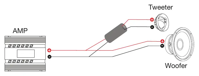
The crossover connects the amplifier to the tweeter and the woofer. Ensure the positive (+) and negative (-) terminals are connected correctly from the amplifier to the crossover input, and then to the respective tweeter and woofer units.
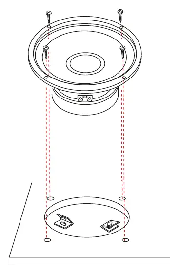
Woofer Mounting
The woofer is designed for standard installation. Use the provided screws and mounting clips to secure the woofer to the mounting surface. Ensure the surface is flat and stable to prevent vibration.
Tweeter Mounting
There are two primary methods for mounting the tweeters:
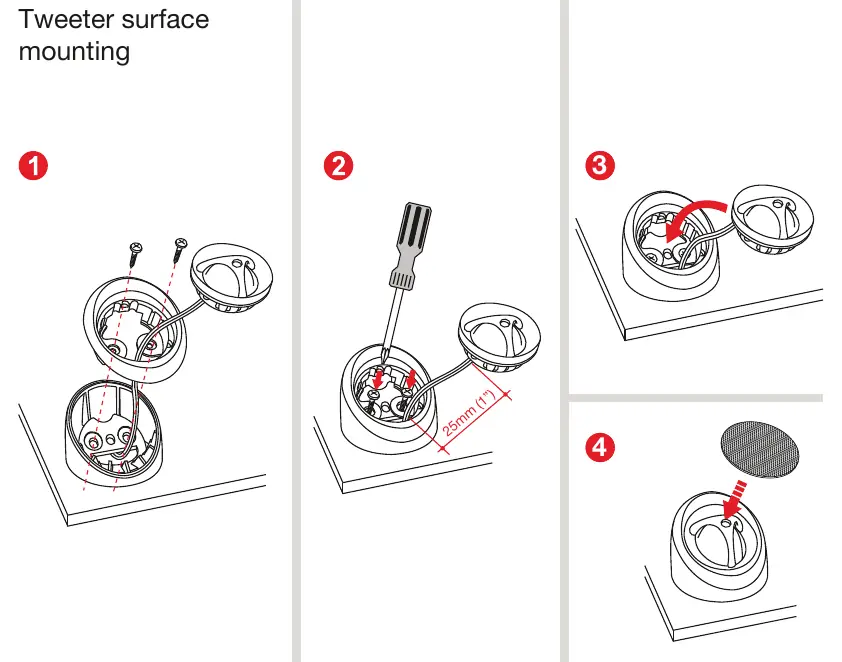
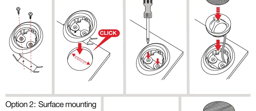
- Option 1: Flush mounting - Requires a 50 mm (1.96") cutout. Insert the tweeter housing into the cutout until it clicks into place.
- Option 2: Surface mounting - Use the provided housing to mount the tweeter directly onto the surface using screws.
Specifications
The system features a nominal impedance of 4 ohm and a power handling of 90W (180W max). The frequency response ranges from 60-22,000 Hz. The woofer has a 30mm voice coil diameter, while the tweeter has a 25mm voice coil diameter.
Practical help
Common problems
Tweeter not fitting in mounting hole
Ensure the cutout diameter is exactly 50 mm (1.96") for flush mounting.
Incorrect sound phase
Double-check that the positive (+) and negative (-) wires from the amplifier are correctly matched to the crossover and speaker terminals.
Before use
- Verify the mounting surface is flat and can support the speaker weight.
- Ensure a 50 mm (1.96") hole is available if choosing flush mounting for the tweeter.
- Check that all necessary screws and clips are present as listed in the content section.
- Confirm amplifier compatibility with 4 ohm impedance speakers.
Specs in practice
- Nominal Impedance
- 4 ohm; the electrical resistance of the speaker, important for amplifier matching.
- Power Handling
- 90W RMS; the continuous power the speaker can handle without damage.
Images and diagrams
- The crossover diagram illustrates the wiring path from the amplifier to the tweeter and woofer.
- The flush mounting diagram shows the 4-step process: preparing the hole, inserting the housing, securing it, and placing the tweeter.
Model compatibility
- Flush mounting requires a specific 50 mm (1.96") cutout.

Manual page author
Emily Carter
User documentation editor
Prepares concise manual descriptions and highlights the most useful setup, operation, and maintenance information for readers.