Automotive / Car Audio
Cerwin Vega CVPRO Series Amplifier User Manual
Quick guide for Cerwin Vega CVPRO Series amplifiers (CUPRO2K4, CUPRO3K, CUPRO5K). Includes installation, wiring diagrams, troubleshooting, and specifications.
Table of contents
Manual images
Click an image to enlargeQuick guide from the manual
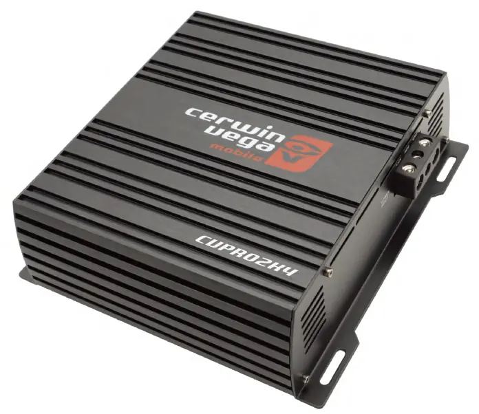
This manual covers the Cerwin Vega CVPRO Series amplifiers, including models CUPRO2K4, CUPRO3K, and CUPRO5K. These are high-performance Class D amplifiers designed for car audio systems. Key requirements include a 12V DC negative ground system and a minimum system impedance of 1 ohm. Professional installation by an authorized retailer is recommended for optimal performance and warranty coverage.
Installation
Proper installation is critical for performance and safety. Follow these guidelines:
- Vehicle Electrical System: Ensure your vehicle's charging system can handle the load. Use 1/0 gauge wire (OFC, not CCA).
- Mounting: Choose a location with adequate ventilation. Avoid mounting on carpet, plastic, or combustible materials. Ensure the amplifier is not exposed to direct heat, moisture, or dust.
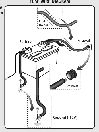
- Wiring: Disconnect the negative battery lead before starting. Install an external fuse on the positive power lead within 18 inches of the battery.
- Grounding: Connect the ground wire directly to the car chassis to minimize resistance and noise.
Functions
The amplifier features several controls to fine-tune your audio:
- Gain: Adjusts the input sensitivity (150mV-12V). This is not a volume control.
- Xovers: Select High Pass or Low Pass filters depending on your speaker setup.
- Bass Boost: Adds up to +12dB of boost at 35Hz-70Hz.
- Subsonic: High Pass filter to protect woofers from over-excursion in ported enclosures.
- Bass Remote: Included with CUPRO3K and CUPRO5K for remote level control.
System Diagrams
The manual provides specific wiring configurations for different setups:
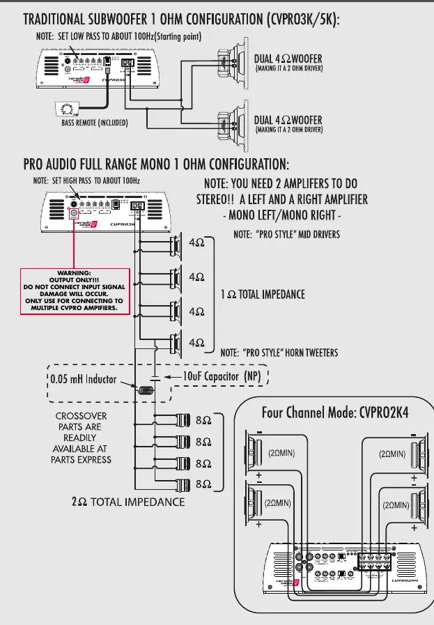
- Traditional Subwoofer 1 Ohm Configuration: For CUPRO3K/5K, set Low Pass to about 100Hz.
- Pro Audio Full Range Mono 1 Ohm Configuration: Requires two amplifiers for stereo operation. Set High Pass to about 100Hz.
- Four Channel Mode: Available for the CUPRO2K4 model.
Troubleshooting
If you encounter issues, check the following:
- No Power: Verify voltage at the amplifier (11.5V-16.1V) with a multimeter. Check the ground connection and the battery fuse.
- Protection Light: Check for high voltage (exceeding 16.1V), thermal issues (ensure ventilation), or short circuits in speaker leads.
- No Sound: Check head unit balance, speaker connections, and input sensitivity settings.
- Frequent Shutdown: Usually indicates thermal shutdown. Ensure impedance is not too low and ventilation is adequate.
Specifications
The CVPRO series amplifiers are Class D, 12V DC powered units. They feature variable High-Pass (50Hz-6kHz/20kHz) and Low-Pass (15Hz-1kHz) crossovers. Output impedance is stable down to 1 ohm.
Warranty
Cerwin Vega provides a one-year warranty against defects in material and workmanship, applicable only to the original purchaser who bought the product from an authorized retailer in the United States.
Practical help
Common problems
No Power
Check voltage at the amplifier (11.5V-16.1V) with a multimeter, verify ground connection, and check the battery fuse.
Protection Light On
Check for high voltage (>16.1V), thermal issues (ensure ventilation), or short circuits in speaker wires.
No Sound
Check head unit balance, speaker connections, and input sensitivity level.
Frequent Thermal Shutdown
Ensure impedance is not lower than recommended, check for damaged speakers, and improve ventilation.
Before use
- Ensure vehicle electrical system is in good condition.
- Use 1/0 gauge wire (OFC).
- Install an external fuse within 18 inches of the battery.
- Ensure total system impedance is not less than 1 ohm.
- Disconnect negative battery lead before making connections.
Specs in practice
- 1 Ohm Stable
- The amplifier can safely drive a load with a minimum impedance of 1 ohm.
- Variable Crossover
- Allows adjustment of frequency ranges (High-Pass/Low-Pass) to match speakers.
Images and diagrams
- Fuse Wire Diagram: Illustrates the connection from the battery to the fuse holder and then to the amplifier.
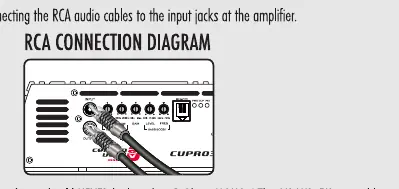
- RCA Connection Diagram: Shows correct input/output connections to avoid damage.
- System Diagrams: Provides wiring examples for subwoofer and full-range configurations.
Model compatibility
- Designed for 12V DC negative ground systems.
- CUPRO3K and CUPRO5K include a bass remote.
- Do not connect input signal to the output terminals.

Manual page author
Michael Turner
Technical manual editor
Reviews PDF manuals for structure, safety notes, and practical product details so readers can find the right information quickly.