Tools / Generators
Installation Guide for Champion 12.5-KW Home Standby Generator
Quick installation guide for the Champion 12.5-KW Home Standby Generator. Includes essential site preparation, fuel system requirements, and electrical wiring specifications.
Table of contents
Quick Installation Overview
This document provides essential installation guidelines for the Champion 12.5-KW Home Standby Generator. It covers site preparation, fuel system requirements, and electrical wiring. Always refer to the full installation manual and local codes before beginning the installation process.
Generator Placement
Proper placement is critical for safety and performance. The generator must be placed on a level surface to ensure proper water runoff and drainage.
- Pad Preparation: Dig an area 5 inches (12.7 cm) deep that is 6 inches (15.2 cm) longer and wider than the generator footprint (49 inches x 28 inches). Fill with pea gravel, sand, or crushed stone. The final stone level must be 2 to 3 inches higher than the original ground level.
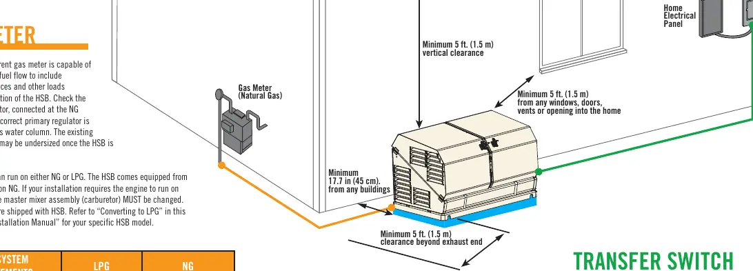
- Clearance Requirements: Maintain a minimum vertical clearance of 5 feet (1.5 m) from windows, doors, vents, or openings into the home. Maintain a minimum distance of 17.7 inches (45 cm) from any building walls. Ensure a minimum of 5 feet (1.5 m) clearance beyond the exhaust end.
- Concrete Pad: A concrete pad is not required unless mandated by local, state, or federal codes, or in areas with high wind potential.
Fuel System Requirements
The generator engine can run on either Natural Gas (NG) or Liquid Propane Gas (LPG). The unit comes factory-equipped for NG.
- LPG Conversion: If using LPG, the orifices in the master mixer assembly (carburetor) must be changed. These orifices are included with the generator.
- Fuel Supply Pressure: For LPG, 10-12 inch WC is required. For NG, 5-7/3.5-5 inch WC is required.
- Pipe Sizing: Pipe size depends on the total length of the run. For example, at 25 ft, use 3/4 inch pipe for both LPG and NG. At 100 ft, use 1 inch pipe for both. If the calculated pipe run is below tabulated maximums, use a larger pipe size.
Electrical Installation
The installation requires 10 wires from the generator to the Transfer Switch (ATS) with a minimum rating of 300 volts.
- Wire Sizing: Use the following guidelines for wire gauge based on length:
- 1-115 ft (1-35 m): No. 18 AWG
- 116-185 ft (36-56 m): No. 16 AWG
- 186-295 ft (57-89 m): No. 14 AWG
- 296-460 ft (90-140 m): No. 12 AWG
- Note: The system also requires 4 power wires; size these accordingly.
Manufacturer information
Champion Power Equipment
Practical help
Common problems
Using LPG fuel
You must change the orifices in the master mixer assembly (carburetor) using the parts shipped with the generator.
Water pooling around the generator
Ensure the mounting pad is 2-3 inches higher than the original ground level and uses a gravel/sand mixture for drainage.
Gas meter capacity
Verify that the current gas meter can provide enough fuel flow for household appliances plus the generator.
Before use
- Check the NG primary regulator (should be set to 6-8 inches water column).
- Ensure the mounting pad is level.
- Verify local codes regarding concrete pad requirements.
- Confirm the distance from combustible walls is at least 17.7 inches (45 cm).
- Ensure 5 feet of clearance from all home openings.
Specs in practice
- Fuel Supply Pressure (LPG)
- 10-12 inch WC
- Fuel Supply Pressure (NG)
- 5-7/3.5-5 inch WC
- Minimum Clearance (Buildings)
- 17.7 inches (45 cm)
- Minimum Clearance (Openings)
- 5 feet (1.5 m)
Images and diagrams
- The diagram illustrates the required clearances from buildings, windows, and doors.
- The wiring table correlates wire length with the required AWG size.
Model compatibility
- Compatible with Natural Gas (NG) and Liquid Propane Gas (LPG).
- Requires 10 wires from generator to ATS with a minimum rating of 300 volts.

Manual page author
Emily Carter
User documentation editor
Prepares concise manual descriptions and highlights the most useful setup, operation, and maintenance information for readers.