Tools / Generators
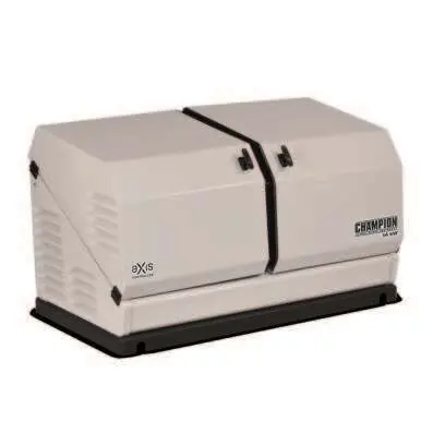
Installation Manual for Champion 14kW Home Standby Generator
A comprehensive installation and setup guide for the Champion 14kW Home Standby Generator. Includes site selection, fuel requirements, battery installation, wiring, and troubleshooting procedures.
Table of contents
Manual images
Click an image to enlargeImportant Information from the Manual
This document provides essential instructions for the installation, setup, and testing of the Champion 14kW Home Standby Generator. It is intended for use by qualified electricians or installation technicians. Always comply with local, state, and national electrical and building codes (NFPA 37, NFPA 54, NFPA 58, NFPA 70).
Safety Precautions
DANGER: Generator exhaust contains carbon monoxide, a poisonous gas. Install and operate outdoors only. Ensure exhaust is directed away from windows, doors, and ventilation intakes.
WARNING: Natural Gas (NG) and Liquefied Petroleum Gas (LPG) are highly explosive. Ensure no leaks are present. Do not use this generator for life support applications.
Site Selection and Placement
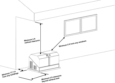
The generator must be installed outdoors. Maintain a minimum clearance of 17.7 inches (45 cm) from the backside of the generator to any combustible wall. Ensure the unit is placed on a level surface, such as a concrete pad or a base of pea gravel/crushed stone, to facilitate drainage.
Installation Preparation
- Fuel Requirements: The unit is factory-set for Natural Gas (NG). If using LPG, you must change the orifices in the Master Mixer Assembly (carburetor).
- Fuel Pipe Sizing: Ensure gas supply lines are sized correctly for 100% load BTU rating. Install a sediment trap and an accessible manual full-flow shut-off valve.
- Battery Installation: The starting system is 24V DC. Install two 12V Group U1 batteries in series. Apply dielectric grease to posts to prevent corrosion.
Wiring and Connections
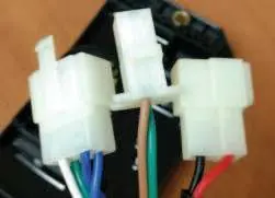
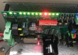
All power cables must enter the enclosure through provided knockouts. Ensure conduit entry maintains the Type 3R rating. The aXis Controller is required for full functionality, including load management and wireless features. If connecting to a non-aXis ATS, a two-wire connection is required, which will disable some advanced features.
Commissioning and Testing
Before operation, perform a full system check:
- Verify all electrical connections are tight.
- Perform a no-load test to verify voltage and frequency.
- Perform a load test using the ATS test button to verify system performance under load.
- Ensure the generator is in AUTO mode for standby operation.
Troubleshooting
If the generator fails to start, check for active fault codes, ensure the controller is in AUTO mode, verify fuel supply, and check battery connections. If the engine runs rough, inspect fuel jets and spark plugs. For AC output issues, check all circuit breakers.

Maintenance
Regularly inspect the generator for debris, check oil levels, and ensure battery connections are clean. Refer to the maintenance schedule in the operator's manual.
Manufacturer information
Champion Power Equipment
Practical help
Common problems
Engine will not crank
Ensure controller is in AUTO mode, check battery connections/charge, and identify any active fault codes.
Engine cranks but will not start
Check fuel supply, verify fuel pressure, check for fault codes, and ensure spark plug wire is connected.
Engine runs rough
Check fuel jets (NG vs LPG), inspect/replace spark plug, and check for generator overload.
No AC output
Check that all circuit breakers (main, transfer switch, standby) are in the ON position.
Before use
- Ensure installation is outdoors with proper clearances (17.7 inches from combustible walls).
- Verify fuel type (NG or LPG) and install correct jets if necessary.
- Install two 12V Group U1 batteries in series for 24V system.
- Check engine oil level (5W-30 Full Synthetic).
- Ensure all electrical connections are tight and properly wired.
- Perform a no-load and load test before relying on the system.
Specs in practice
- Maximum continuous power (LPG)
- 14 kW
- Maximum continuous power (NG)
- 12.5 kW
- Rated voltage
- 120/240V
- Oil capacity
- 1.6 qt (1.5 L)
Images and diagrams
- Placement diagram illustrates 17.7-inch clearance from combustible walls and 5-foot clearance from windows/openings.
- Wiring diagrams for aXis Controller pins and DIP switches are provided for reference.
Model compatibility
- Requires Champion aXis Controller ATS for full functionality.
- Not compatible with standard ATS models 100947, 100950, 100952, 101283, and 101380.

Manual page author
Michael Turner
Technical manual editor
Reviews PDF manuals for structure, safety notes, and practical product details so readers can find the right information quickly.