Lighting / Wireless Control
User Manual for City Theatrical Multiverse Receiver Card 2.4GHz 5906
Comprehensive user guide for the City Theatrical Multiverse Receiver Card 2.4GHz (5906). Includes installation, configuration for Basic and Advanced modes, pinout diagrams, troubleshooting, and technical specifications.
Quick answers from the manual
Quick answer
- The 5906 Multiverse Receiver Card is a 2.4GHz wireless DMX/RDM receiver. It supports Basic mode (DMX output) and Advanced mode (0-10V/PWM output). Configuration is managed via USB or RDM. p. 3, 6
Key actions
- Reset Factory Defaults p. 6
- Configure via USB p. 6
First start
- Power the card via the USB Micro-B connection or the 20-pin header (5-30Vdc). p. 6, 8
Problems and fixes
Unit does not power up
Check pinout, power orientation, and input voltage (5-30Vdc).
p. 17
DMX devices flashing/moving
Check for RDM traffic interference or ensure proper DMX termination.
p. 17Maintenance and reset
- Hold the SHoW ID Selector Switch for 5 seconds. p. 6
Technical specifications
| Parameter | Value | Meaning | Pages |
|---|---|---|---|
| Input Voltage | 5-30Vdc | Operating voltage range. | p. 5 |
| Frequency | 2.4GHz | Operating frequency. | p. 5 |
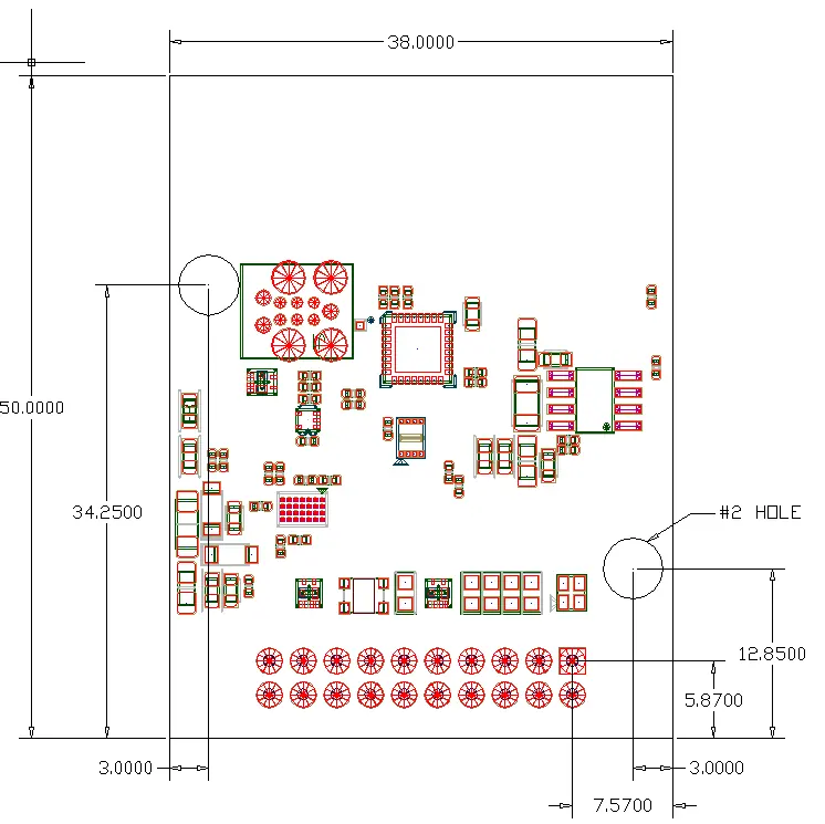
| Dimensions | 50mm x 38mm | Physical footprint. | p. 5 |
Where to find it in the PDF
- Specifications p. 5
- Pinout (Basic) p. 8
- Pinout (Advanced) p. 11
Table of contents
Manual images
Click an image to enlargeQuick Guide from the Manual
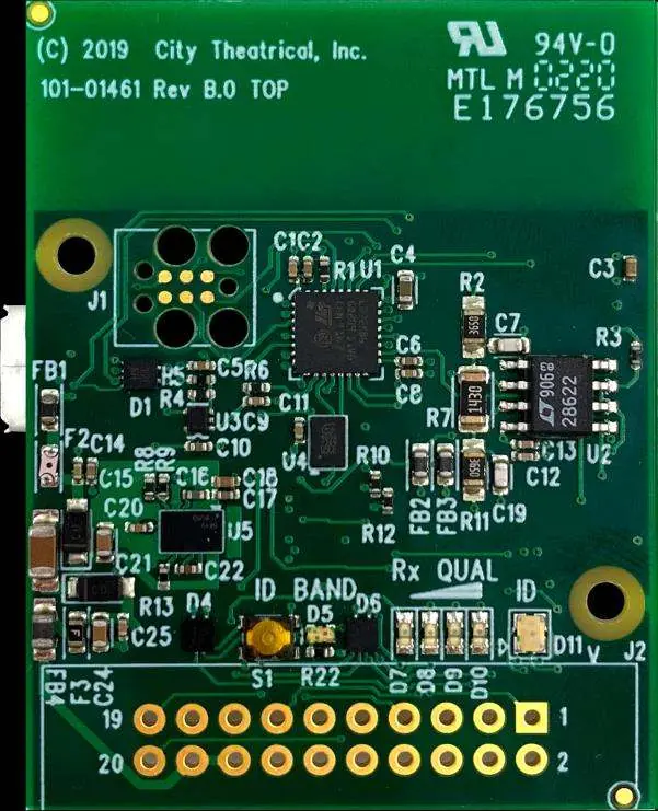
The City Theatrical Multiverse Receiver Card 2.4GHz (5906) is a circuit board-mounted device designed to implement wireless DMX/RDM. It operates in two modes: Basic (DMX output) and Advanced (0-10V/PWM output). Configuration is performed via the City Theatrical USB Configurator (PC/Mac) or RDM.
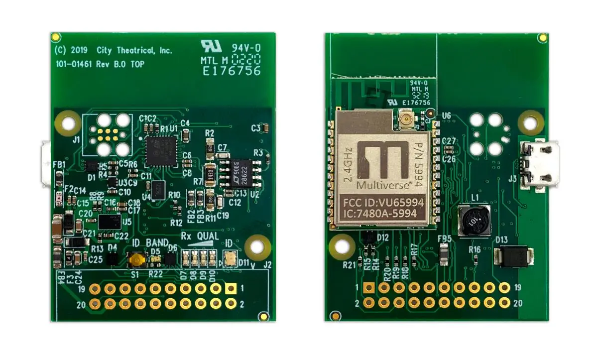
Installation and Wiring
The card features a 20-pin header for I/O connections. Ensure the input voltage is between 5V and 30Vdc. For the 0-10V feature, a minimum of 11V is required.
Basic Signal Pinout
- Pin 11: DMX Common
- Pin 12: DMX Data Minus
- Pin 13: DMX Data Plus
- Pin 17: Signal Ground
- Pin 18: +5-30V DC Input
Refer to the full pinout table in the manual for Advanced Mode configurations, which repurpose LED pins for PWM outputs.
Configuration
The receiver can be configured using the free City Theatrical USB Configurator program. Connect the card via the USB Micro-B connector to a PC or Mac. The card acts as a virtual serial port.
Resetting Factory Defaults
To reset the card to factory defaults, hold the SHoW ID Selector Switch for five seconds. The four signal quality lights will flash in unison to confirm the reset.
LED Indicators
- Band LED: Indicates the mode (Green for Multiverse 2.4GHz, Yellow for SHoW DMX Neo 2.4GHz).
- ID/Status LED: Blinks when no DMX is received; turns solid when DMX is received.
- Rx Quality LEDs: Four LEDs representing signal quality. For best performance, at least two LEDs should be lit.
Advanced Features
Advanced mode allows for 0-10V control signal output and four PWM control outputs. These features are configurable via the USB Configurator program. PWM outputs are linear in respect to the DMX control input and have 8-bit resolution.
Troubleshooting
- Unit does not power up: Check pinout, power orientation, and ensure input voltage meets the 5-30Vdc specification.
- No control: Verify the transmitter is in range and data is being sent. Reset factory defaults if necessary.
- DMX devices flashing/moving: Check for RDM traffic interference or ensure the DMX chain is properly terminated with a 120Ω resistor.
- 0-10V/PWM not working: Ensure the feature is enabled in the USB configurator and check the DMX address settings.
Practical help
Common problems
Unit does not power up
Check pinout for proper power orientation, use a multimeter to check for short circuits, and confirm input voltage is 5-30Vdc.
No DMX control
Check status indicators to confirm a transmitter is in range, reset factory defaults, and verify antenna mode.
DMX devices flashing or moving unreliably
Confirm data lines are connected correctly, ensure the DMX chain is terminated with a 120Ω resistor, and check for RDM traffic interference.
0-10V output not working
Ensure 0-10V mode is enabled in the USB configurator, confirm DMX address, and verify supply voltage is at least 11V.
Before use
- Verify input voltage is between 5V and 30Vdc
- Ensure antenna is connected (internal or external)
- Download the City Theatrical USB Configurator for PC/Mac
- Check wiring pinout for Basic or Advanced mode requirements
Specs in practice
- Voltage Range
- 5-30Vdc input required for operation.
Images and diagrams
- Figure 1 illustrates the top and bottom PCB layout, including the location of the SHoW ID Selector Switch and I/O connection points.
- Figure 3 provides the physical dimensions of the board.
Model compatibility
- Compatible with ANSI E1.11 DMX512-A and E1.20 RDM.
- Requires City Theatrical USB Configurator for advanced settings.
- Approved antennas must be used; see Table 17 for the list.

Manual page author
Emily Carter
User documentation editor
Prepares concise manual descriptions and highlights the most useful setup, operation, and maintenance information for readers.