Automotive / Garage Equipment
Installation Guide for CLAS MA 1000 Modular Workshop Kitchen
Complete assembly and installation guide for the CLAS MA 1000 Modular Workshop Kitchen. Includes parts list, step-by-step assembly instructions, and safety requirements.
Quick answers from the manual
Quick answer
- The CLAS MA 1000 is a modular workshop kitchen. Assembly requires two people, approximately two hours, and basic tools including a drill for wall anchoring. p. 3, 7
Key actions
- Assemble in final location p. 3, 7
- Secure to wall p. 6, 11
First start
- Level the work surface p. 6, 11
Where to find it in the PDF
- Parts List p. 3, 4, 7, 8
- Assembly Steps p. 5, 6, 9, 10
Table of contents
Manual images
Click an image to enlargeQuick guide from the manual
The CLAS MA 1000 is a modular workshop kitchen system. For a successful installation, it is essential to allocate at least two hours and have two people available for the assembly process. The furniture should be assembled in its final location, as it is difficult to move once fully installed. Always wear appropriate personal protective equipment (PPE), such as safety glasses and gloves, during assembly.
Preparation and Safety
Before beginning the assembly, ensure you have the following tools available:
- Allen key (provided with the kit)
- Screwdriver
- Drill (required for wall anchoring)
- Spirit level
- Measuring tape
Verify that all parts listed in the components section are present before starting.
Assembly Instructions
Follow these steps to assemble the workshop kitchen:
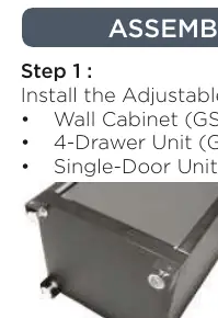
- Feet Installation: Install the adjustable feet (GSW-14) and fixed feet (GSW-15 + GSW-18) under the wall cabinet (GSW-01), 4-drawer unit (GSW-03), and single-door unit (GSW-04).
- Positioning: Place the units in their final position. Ensure there is a 680 mm gap between the 4-drawer unit and the single-door unit.
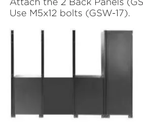
- Structure: Install the four vertical posts (GSW-12) at the back. Attach the two back panels (GSW-24) to the two central posts using M5x12 bolts (GSW-17).
- Panels: Attach the six perforated panels (GSW-06) to the posts above the units using M5x12 bolts.
- Wall Cabinets: Mount the three wall cabinets (GSW-05) above the perforated panels using M5x12 bolts.
- Worktop and Plinths: Attach the wooden worktop (GSW-13) and install all base plinths (GSW-09, GSW-10, GSW-11) under the units using M5x12 bolts.
- Securing: Screw the inside of the wall cabinet and the back of each post into the wooden worktop using M4x20 bolts (GSW-19).
- Shelving: Install the shelf supports (GSW-16) and place the shelves (GSW-07, GSW-08) inside the cabinets.
Final Adjustments and Anchoring
Once the structure is assembled, perform the following final steps:

- Leveling: Use the provided Allen key to adjust the adjustable feet (GSW-14) until the work surface is perfectly level.
- Wall Anchoring: For safety, secure the structure to the wall. Insert the mounting insert (GSW-23) into the posts (GSW-12). Fasten the screws (GSW-21) through the anchor and into the M4x30 wall plugs (GSW-22) that have been pre-installed in the wall.
Manufacturer information
CLAS EQUIPEMENTS
Practical help
Common problems
Difficulty moving the unit after assembly
The unit is heavy and modular; it is designed to be assembled in its final location. Avoid moving it once installed.
Unstable or uneven work surface
Use the provided Allen key to adjust the adjustable feet (GSW-14) until the work surface is level.
Before use
- Ensure two people are available for assembly.
- Allocate at least two hours for the process.
- Wear appropriate PPE (glasses, gloves).
- Have required tools ready: screwdriver, drill, spirit level, measuring tape.
- Verify all parts (GSW-01 to GSW-24) are present.
Images and diagrams
- The manual provides a detailed parts list with images for identification.
- Assembly steps are illustrated with clear diagrams showing the sequence of connecting cabinets, posts, and panels.
Model compatibility
- The unit requires wall anchoring for safety.
- The assembly is designed for a 2.6m modular configuration.

Manual page author
Emily Carter
User documentation editor
Prepares concise manual descriptions and highlights the most useful setup, operation, and maintenance information for readers.