Automotive / Garage Equipment
User Manual for CLAS PE 2001T 2-Column Asymmetric Lift
Comprehensive user guide for the CLAS PE 2001T 2-column asymmetric lift. Includes installation, safety, calibration, maintenance, and troubleshooting procedures.
Quick answers from the manual
Quick answer
- The CLAS PE 2001T is a 4-ton, 2-column asymmetric lift. It requires a 400V 3-phase power supply and must be installed on a solid concrete floor by a professional. p. 1, 7, 31
Key actions
- Installation must be performed by a professional on a solid concrete floor. p. 3, 12, 36
- Synchronize carts using the steel wire nut if they are misaligned. p. 17, 41
First start
- Verify power connection and motor rotation direction. p. 16, 40
Problems and fixes
Engine does not work
Check power connection and AC contactor.
p. 19, 43Maintenance and reset
- Change hydraulic oil once a year and lubricate moving parts. p. 18, 42
Technical specifications
| Parameter | Value | Meaning | Pages |
|---|---|---|---|
| Capacity | 4000kg | Maximum load capacity | p. 7, 31 |
| Motor Power | 2.2 KW | Power of the motor | p. 7, 31 |
Where to find it in the PDF
- Warranty p. 3, 27
- Installation p. 12, 36
- Troubleshooting p. 19, 43
Table of contents
Manual images
Click an image to enlargeQuick guide from the manual
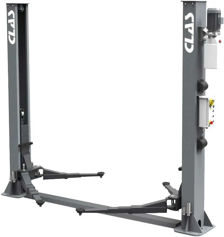
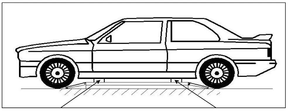
The CLAS PE 2001T is a 4-ton, 2-column asymmetric lift designed for vehicle maintenance. Important: Installation and commissioning must be performed by a professional. The lift requires a solid concrete floor (thickness ≥ 200mm) and a 400V 3-phase power supply. Always ensure the vehicle's center of gravity is correctly positioned on the arm supports before lifting.
Description
This lift is designed for lifting vehicles up to 4000kg. It features an electromagnetic locking system, safety valves to prevent hydraulic failure, and high-quality Italian hydraulic pumps. The asymmetric design allows for easier access to vehicle doors.
Safety
General Precautions: Never exceed the 4000kg capacity. Do not use the lift to wash vehicles, lift people, or as an elevator. Personnel must remain in the designated control zone during operation. Ensure the area is well-lit and free of oil spills. Never disable safety devices.
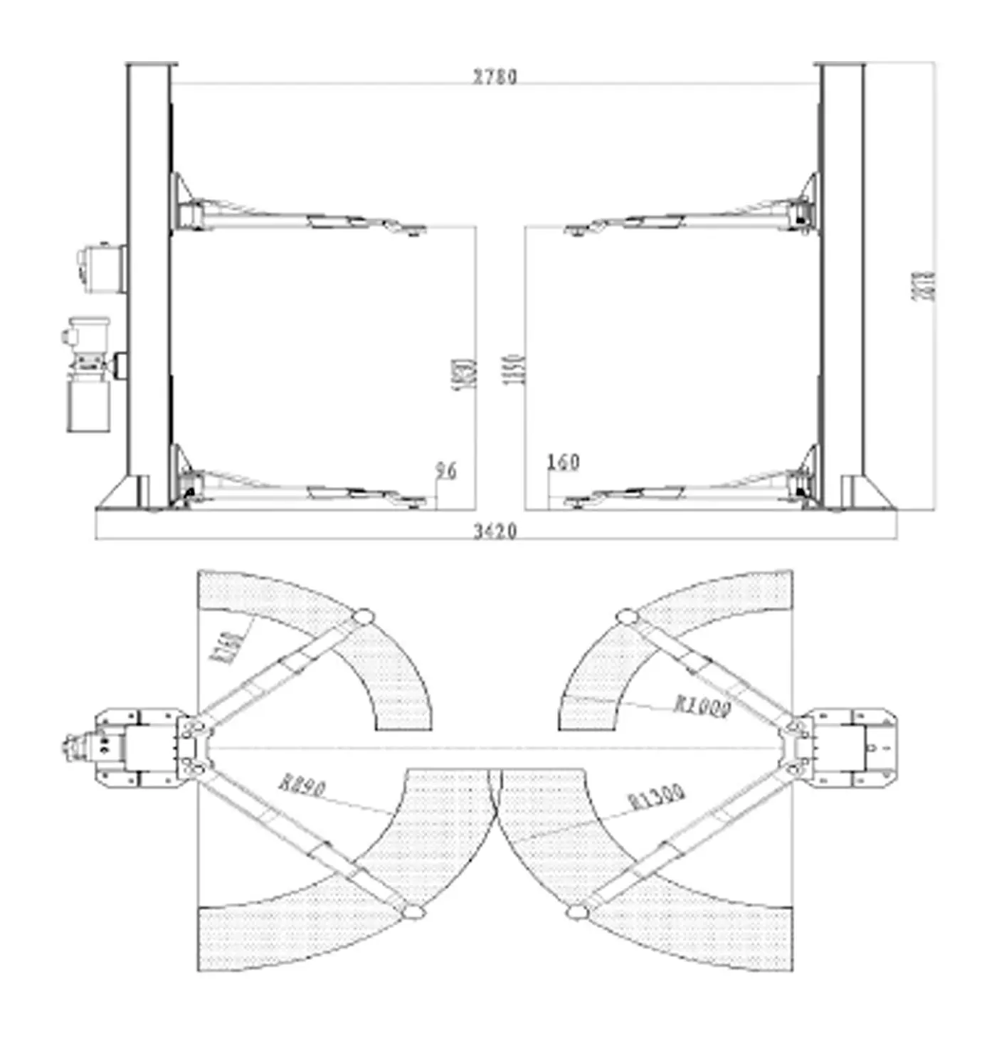
Installation
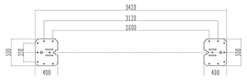
The lift must be installed on a level, solid concrete floor. Requirements: Minimum ceiling height of 4000mm, safety distance of 1200mm from walls. Use the provided anchoring bolts after drilling 20mm holes. Connect the hydraulic pump and electrical system according to the provided diagrams. Ensure the steel cables are correctly routed through the pulleys and synchronized.
Calibration
After installation, perform the calibration procedure: verify power connection and motor rotation. Use the 'UP' button to ensure electromagnets release the safety locks and carts move simultaneously. Use the 'DOWN' button to verify the lowering mechanism. If carts are misaligned, adjust the steel wire nut.
Maintenance and Care
Regular maintenance is essential for safety. Lubricate all pivots and sliding blocks regularly. Change the hydraulic oil once a year. Check steel cables for abrasions or defects; if found, do not use the lift and contact the manufacturer. When refilling oil, use a filter.
Troubleshooting
If the engine does not work, check the power connection and AC contactor. If the motor runs but there is no lifting movement, check the hydraulic oil level, the descent valve, or the parachute valve. If the lift does not lower, ensure the security tooth is released. If carts are misaligned, adjust the steel wire nut.
Manufacturer information
CLAS EQUIPEMENTS
Practical help
Common problems
The engine does not work
Check if the power cable is plugged in. If the AC contactor is faulty, replace it.
Motor runs but no lifting movement
Check hydraulic oil level, ensure the descent valve is not stuck, or clean the parachute valve.
Lift does not lower
The security tooth may be engaged. Perform a short upward lift to release it, then try lowering again.
Carts are misaligned
Adjust the steel wire nut to synchronize the traction force.
Before use
- Verify the vehicle weight does not exceed 4000kg.
- Ensure the vehicle is correctly positioned with the center of gravity on the arm supports.
- Check that no personnel are in the danger zone.
- Verify that the floor is level and concrete.
- Check for any oil leaks in pipes or joints.
- Ensure all safety devices are engaged and functional.
Specs in practice
- Lifting Height
- Maximum vertical lift of 1900mm.
Images and diagrams
- Floor layout showing dimensions and anchoring points.
- Hydraulic connection diagram.
- Electric circuit diagrams for 220V and 380V.
- Exploded view of the lift components.
Model compatibility
- Indoor use only.
- Requires solid concrete floor with steel reinforcements (thickness ≥ 200mm).
- Not suitable for asphalt floors.

Manual page author
Emily Carter
User documentation editor
Prepares concise manual descriptions and highlights the most useful setup, operation, and maintenance information for readers.