Automotive / Garage Equipment
User Manual for CLAS PE 2001M 2-Column Asymmetric Post Lift
Comprehensive user manual for the CLAS PE 2001M 2-column asymmetric post lift. Includes installation instructions, safety guidelines, calibration procedures, maintenance, and troubleshooting.
Quick answers from the manual
Quick answer
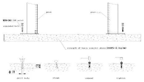
- The CLAS PE 2001M is a 2-column asymmetric post lift with a 4000kg capacity. It requires professional installation on a leveled concrete floor (min 200mm thickness, 3000PSI). p. 7, 12
Key actions
- Adjusting cart synchronization p. 17, 41
- Performing maintenance p. 18, 42
First start
- Calibration procedure p. 16, 40
Problems and fixes
Engine does not work
Check power cable, AC contactor, or UP button.
p. 19, 43Maintenance and reset
- Hydraulic oil replacement p. 18, 42
Technical specifications
| Parameter | Value | Meaning | Pages |
|---|---|---|---|
| Capacity | 4000kg | Max load | p. 7, 31 |
| Power | 2.2 KW | Motor power | p. 7, 31 |
Where to find it in the PDF
- Installation p. 12, 13, 14, 15
- Troubleshooting p. 19, 43
Table of contents
Manual images
Click an image to enlargeQuick Guide from the Manual
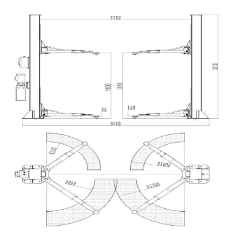
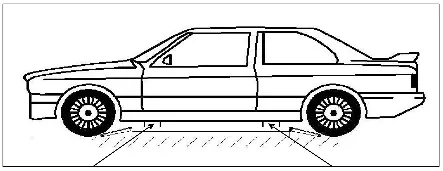
The CLAS PE 2001M is a 2-column asymmetric post lift designed for lifting vehicles up to 4000kg. Installation must be performed by a professional on a perfectly leveled concrete floor with a minimum thickness of 200mm (3000PSI). Always ensure the vehicle is correctly positioned and the center of gravity is within the lifting area.
Description and Functionality
This lift is designed for testing, repairs, and vehicle maintenance. It features an electromagnetic locking system, safety and anti-knock valves to prevent hydraulic failure, and a high-quality Italian hydraulic pump. Each column is equipped with a cylinder for stability during ascent and descent.
Installation Requirements
- Floor: Must be solid concrete, perfectly leveled, with steel reinforcements. Thickness must be at least 200mm.
- Space: Minimum height of 4000mm required. Maintain a safety distance of at least 1200mm from walls.
- Electrical: Ensure proper 3-phase connection (3Ph + N + T) or 230V configuration as specified.
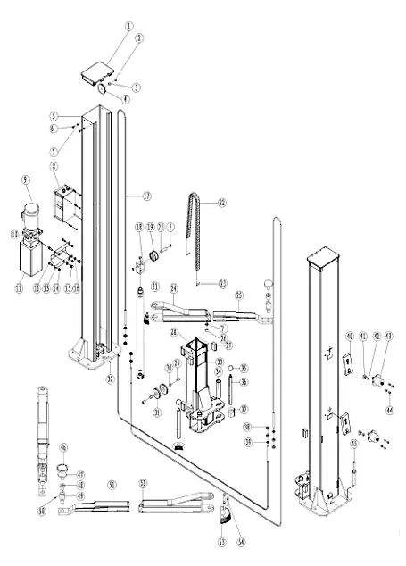
Installation Steps
1. Columns and Anchoring
Anchor the columns to the floor using the provided bolts after drilling 20mm diameter holes. Ensure the depth matches the dowel length.
2. Steel Cables
Connect the steel wire through the trolley, pass it through the upper end of the lift, and connect it to the trolley of the other column. Secure with a nut and ensure correct positioning inside the pulleys.
3. Arms and Safety Devices
Install arms into the slots on the carts and secure extensions with M8x12 bolts. Install the electromagnetic safety lock on the column, adjusting the nut to ensure the device hooks the cart (approx. 30-34mm distance).
4. Hydraulic and Electrical
Place the hydraulic pump on the right column. Connect hydraulic lines as shown in the diagrams. Electrical connections must be performed by qualified personnel according to the provided electrical diagrams.
Calibration
Perform multiple lifting and lowering cycles to tension the steel cables. Use the 'UP' button to verify synchronization of the carts. If they are not synchronized, adjust the steel wire nut. Conduct a load test with maximum capacity, ensuring no personnel are under the load.
Maintenance and Care
- Lubricate all pins, sliding blocks, and moving parts regularly.
- Change hydraulic oil at least once a year.
- Check the integrity of steel cables regularly; if abrasions or defects are found, do not use the lift.
- When refilling oil, use a filter.
Troubleshooting
If the engine does not work, check the power cable, AC contactor, or UP button. If the motor runs but there is no lifting movement, check the hydraulic oil level, descent valve, or parachute valve. If carts are misaligned, adjust the steel wire nut.
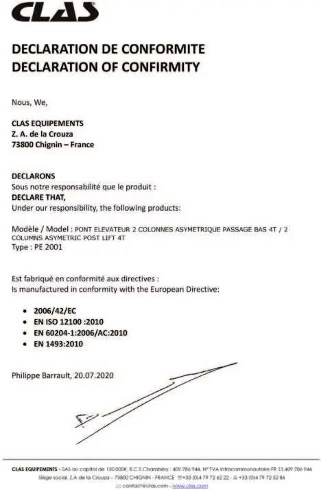
Manufacturer information
CLAS EQUIPEMENTS
Practical help
Common problems
Engine does not work
Check power cable connection, AC contactor, or UP button.
Motor runs but no lifting movement
Check hydraulic oil level, descent valve, or parachute valve.
Carts are misaligned/not synchronized
Twist the steel wire nut to adjust tension.
Spilled oil
Tighten pipes and fittings or replace them.
Before use
- Check hydraulic oil level
- Ensure floor is level and solid
- Verify safety devices are engaged
- Check load distribution
- Ensure no personnel are in the danger zone
- Verify vehicle is correctly positioned
Specs in practice
- Lifting Height
- 1900mm
- Hydraulic Oil
- 13 liters of H46 hydraulic oil
Images and diagrams
- Figure 1: Dimensions of the lift
- Figure 2: Floor layout requirements
- Figure 3: Column installation
- Figure 10: Hydraulic connections
Model compatibility
- Not suitable for spray washing vehicles
- Not for lifting people
- Not for use as an elevator
- Requires 3-phase or 230V power supply

Manual page author
David Miller
Documentation analyst
Organizes user manual content into clear summaries, with attention to model details, product context, and everyday usability.