HVAC / Thermostats & Controls
Condair RDC-NA Digital Wall Humidistat
Quick guide for the Condair RDC-NA digital wall humidistat. Includes installation, wiring diagrams, parameter configuration, sensor calibration, and troubleshooting steps.
Table of contents
Manual images
Click an image to enlargeQuick guide from the manual
The Condair RDC-NA is a digital wall humidistat designed for humidity control. This guide covers the essential installation, wiring, and configuration steps required for operation. Always ensure the device is installed in a protected, accessible location at least 1.5 meters above the floor.
Mounting and Installation
Follow these steps to install the unit:
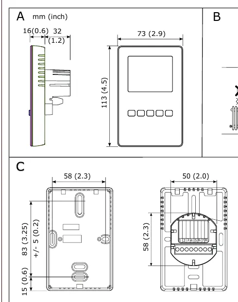
- Location: Mount at least 1.5 m above the floor. Avoid niches, curtains, heat sources, direct air drafts, and direct sunlight.
- Disassembly: Open the housing screw and remove the mounting plate.
- Wiring: Connect wires to the terminals according to the wiring diagram. Use 18-gauge wire (max distance
- Fixing: Secure the mounting plate to the wall box with two screws (plastic screw facing downwards).
- Assembly: Snap the housing onto the mounting plate and secure with the screw (do not overtighten).
LCD Display and Operation
The display shows actual humidity and the setpoint. Control buttons allow for the following operations:
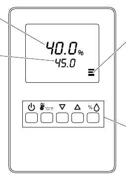
- Power button: Long press to switch On/Off.
- C/F button: Briefly press for no action; long press to switch between °C and °F.
- Up/Down arrows: Briefly press to adjust the setpoint value.
- % button: Briefly press to show %rH value; long press for offset settings.
Configuration and Parameters
The controller has two parameter levels accessible via the keypad:
- User/Display Parameters (Password 0009): Allows changing operation modes, setpoints, power failure behavior, and display content.
- Control Parameters (Password 0241): For expert use only, includes output configuration (min/max setpoints, fan delays).
How to change parameters:
- Press Up/Down buttons simultaneously for 3 seconds.
- Press the % button to start login.
- Use Up/Down buttons to select the code (0009 or 0241) and press % to confirm.
- Navigate parameters with Up/Down, modify with %, and save with %.
Sensor Calibration
If calibration is required:
- Press the % button for > 2 seconds until UI and its value appear.
- Press the % button again to display the calibration value and tool symbol.
- Use Up/Down to calibrate.
- Press the % button to save; the tool symbol disappears.
Troubleshooting
- Err 1: Sensor element is not properly inserted or is defective. Check insertion or replace the sensor.
- Err 2, 3, & 4: Hardware or memory problem. Replace the device.
Technical Specifications
- Power Supply: 24 V AC/DC ± 10%, Max 3 VA.
- Humidity Range: 0–100% RH.
- Analog Output: 0–10 VDC or 0–20mA.
- Environment: 0–50°C (32–122°F), <95% rH non-condensing.
Manufacturer information
Condair
Practical help
Common problems
Err 1 displayed
Sensor element is not properly inserted or is defective. Re-insert or replace the sensor.
Err 2, 3, or 4 displayed
Hardware or memory problem. The device must be replaced.
Before use
- Ensure mounting location is at least 1.5m above the floor.
- Avoid placing the unit in niches, behind curtains, or near heat sources.
- Use 18-gauge wire for connections.
- Ensure the distance from the unit is less than 100 ft.
- Verify power supply is 24 V AC/DC ± 10%.
Specs in practice
- Operating Voltage
- 24 V AC 50/60 Hz or 24 V DC (± 10%).
- Analog Output
- Configurable for 0–10 VDC or 0–20mA signal.
- Humidity Range
- Measures 0–100% RH with ± 3.0% accuracy at 25°C.
Images and diagrams
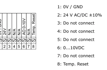
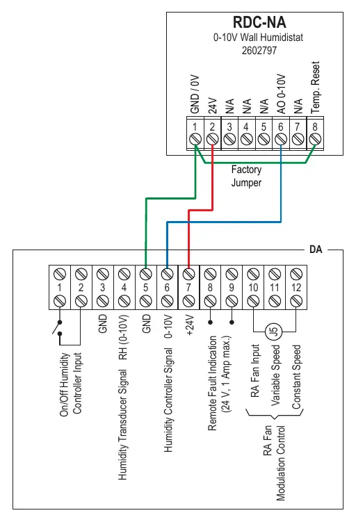
- Wiring diagram shows terminals 1-8 for power, output, and reset functions.
- Mounting diagram illustrates the screw locations and housing removal process.
Model compatibility
- Compatible with 24V AC/DC power sources.
- Requires 18-gauge wiring for optimal performance.

Manual page author
David Miller
Documentation analyst
Organizes user manual content into clear summaries, with attention to model details, product context, and everyday usability.