Electronics / Networking
User Guide for Connect Tech Xtreme/10G Managed Ethernet Switch/Router XDG201
Quick guide for the Connect Tech Xtreme/10G Managed Ethernet Switch/Router (XDG201). Learn about installation, board-to-board connections, CLI and web management, and thermal specifications.
Table of contents
Manual images
Click an image to enlargeQuick guide from the manual
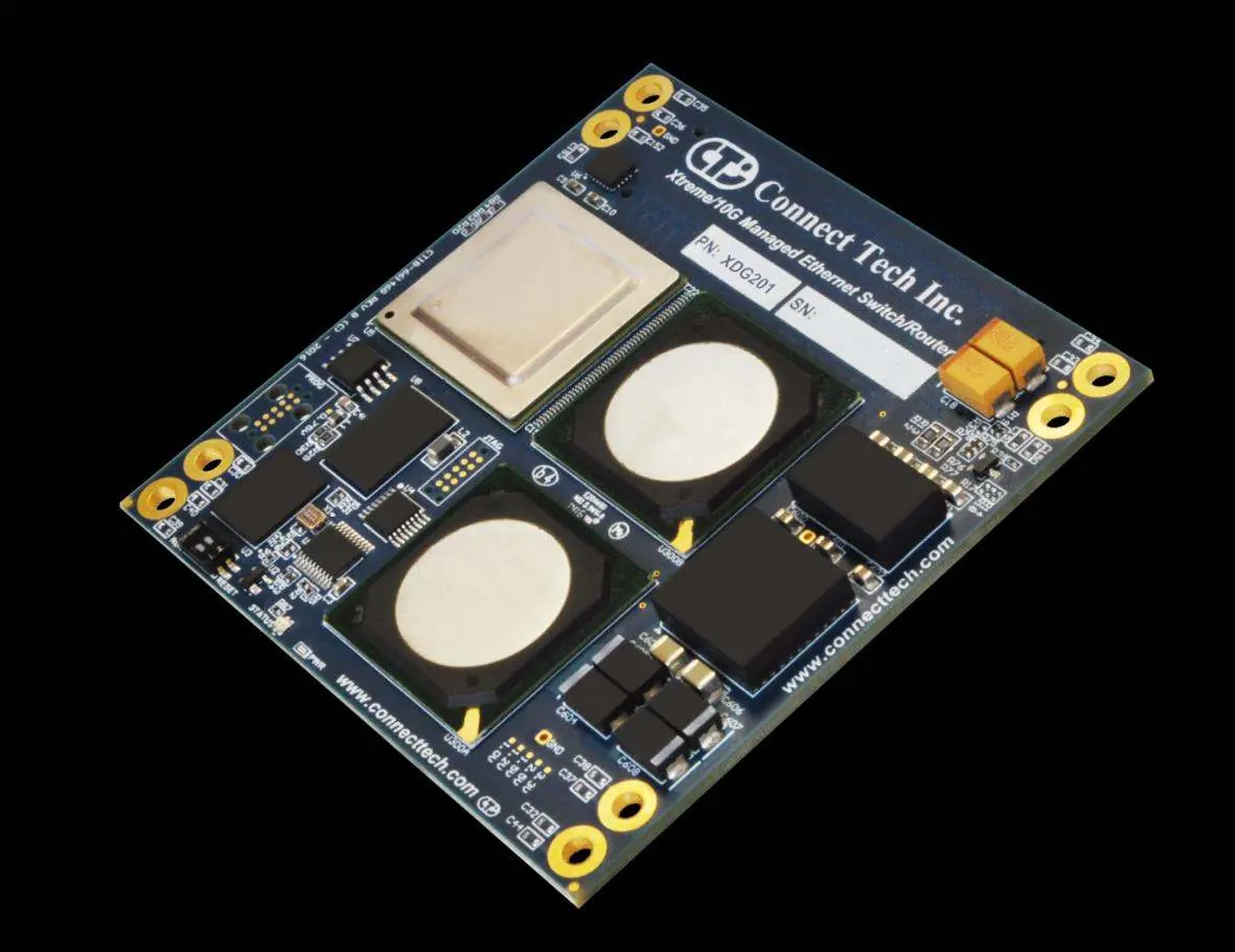
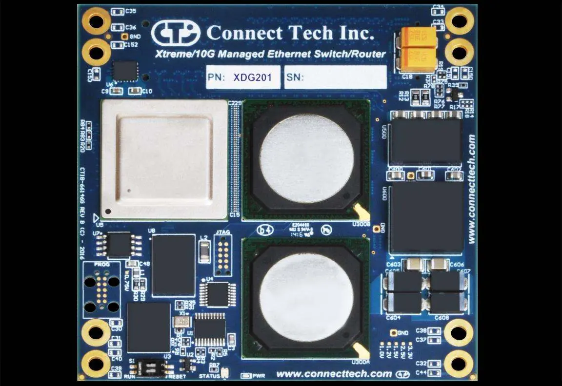
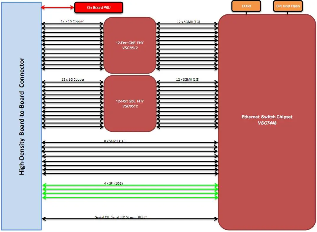
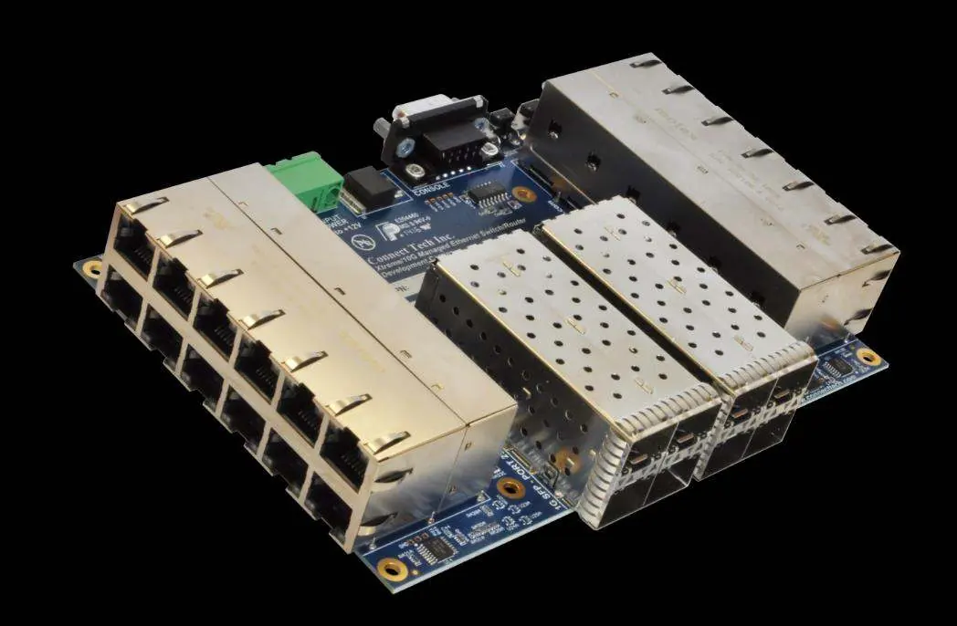
The XDG201 is a high-density, high-port count Layer 2 and Layer 3 network switching module. It is designed as a proprietary form factor module that requires integration into a carrier board (such as the XBG301) for physical connectivity. The device supports 36 total ports, including 4x 10G, 8x 1G (SGMII), and 24x 1G (Copper). Management is available via an external serial port (CLI) or a web interface. The default IP address for web management is 10.10.10.1.
Installation
The XDG201 is a module and must be installed on a carrier board. Follow these steps for installation:
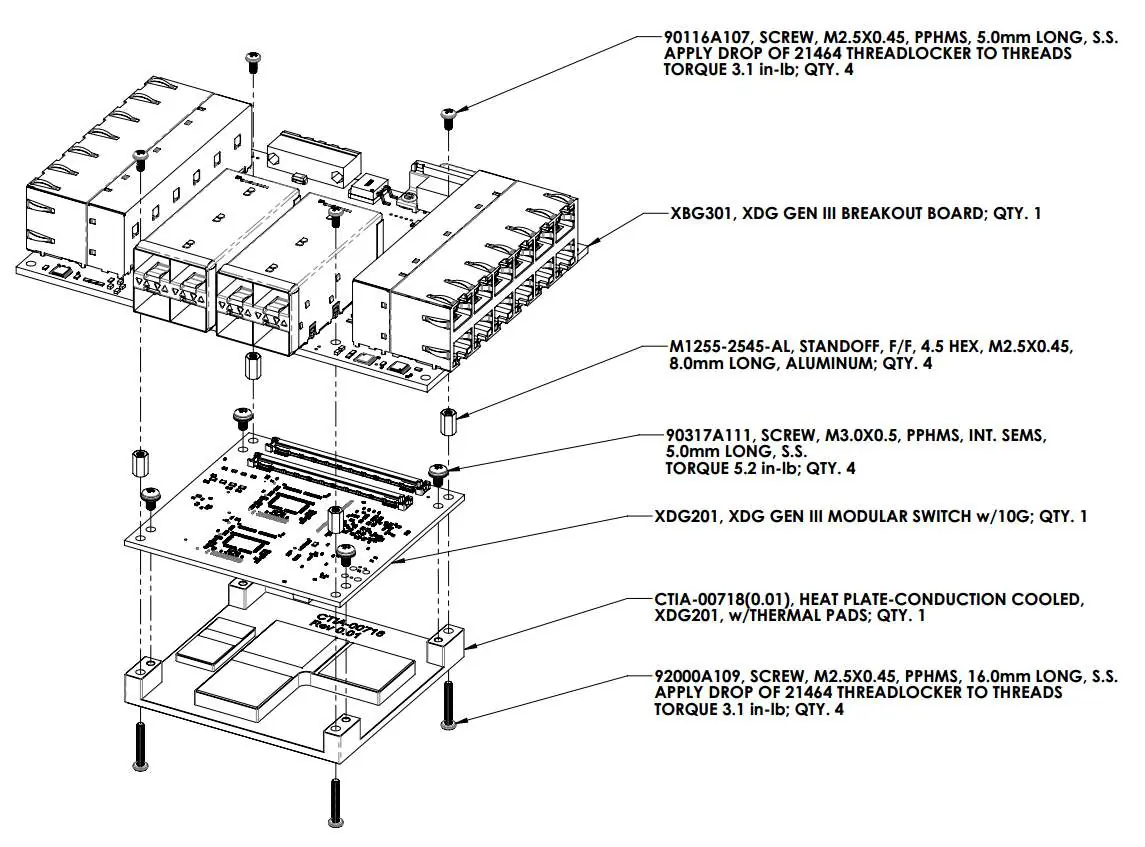
- Install the XHG201 heatplate to the XDG201 module.
- Prepare the breakout or carrier board with 4x M3 8mm standoffs.
- Ensure the carrier board provides +12V DC power.
- Mate the board-to-board connector from the XDG201 module to the carrier board.
- Turn on power to the carrier board to boot the XDG201.
Important: Ensure the S1 DIP switch is set to the RUN position. Moving it to RESET will prevent the board from booting.
Management Interfaces
CLI Management
To access the CLI, connect to the external management serial port using TX, RX, and GND connections. Configure your terminal program (e.g., Putty, RealTerm) with the following settings: Baud Rate 115200, 8 Data Bits, 1 Stop Bit, No Parity. The default login is admin with a blank password.
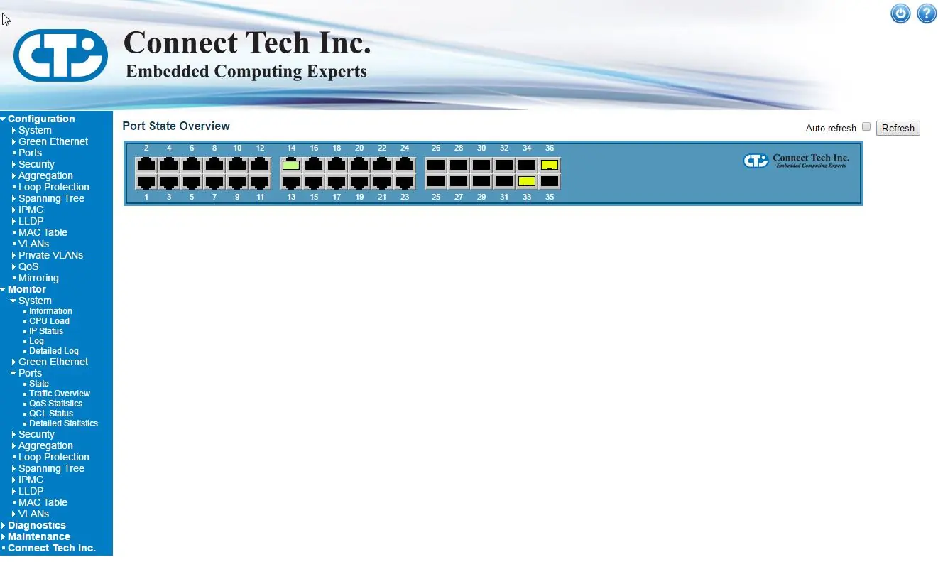
Web Management
There are two methods to access the web interface:
- Default IP: Connect any port to your host PC using a Cat5e cable. Set your PC's IP address to the same subnet (10.10.10.X) and navigate to 10.10.10.1 in a web browser.
- Custom IP: Access the CLI and use the configure terminal, interface vlan 1, and ip address commands to set a static IP on your network.
The default login for the web interface is admin with a blank password.
Breakout Boards and Thermal Details
The XBG301 is a COTS breakout board solution provided by Connect Tech that serves as a reference design platform. It includes full documentation, schematics, and layout files. For thermal management, the XHG201 conduction-cooled heatplate is required to interface the XDG201 to a chassis wall or finned heat sink. It is not intended for standalone operation.
Technical Specifications
- Input Voltage: +4V to +14V DC.
- Operating Temperature: -40°C to +85°C.
- Power Consumption: 24W Max / 14W Idle.
- Dimensions: 85mm x 85mm.
- Switching Capacity: 80Gbps.
Manufacturer information
Connect Tech Inc.
Practical help
Common problems
Device does not boot
Ensure the S1 DIP switch is set to the RUN position, not RESET.
Cannot access web interface
Ensure your host PC is on the same subnet (10.10.10.X) as the default IP 10.10.10.1.
No power to module
Verify that the carrier board is supplying +12V DC to the input power connector.
Before use
- Install XHG201 heatplate to XDG201 module.
- Prepare carrier board with 4x M3 8mm standoffs.
- Verify power supply is +12V DC.
- Ensure S1 switch is in RUN position.
Specs in practice
- Input Voltage
- +4V to +14V DC range.
- Operating Temp
- -40°C to +85°C.
- Max Bandwidth
- 80Gbps.
Images and diagrams
- Top Side: Shows connector locations and S1 switch.
- Assembly Drawing: Shows mounting of XDG201 to XBG301 carrier board.
Model compatibility
- Requires carrier board (e.g., XBG301) for physical interface.
- Supports CISCO Compatible/Equivalent GLC-T transceivers.

Manual page author
Emily Carter
User documentation editor
Prepares concise manual descriptions and highlights the most useful setup, operation, and maintenance information for readers.