General / Accessories
Fiber Optic Cable Corning ALTOS Lite 48F 50µm OM4
Technical guide for the Corning ALTOS Lite 48F 50µm OM4 fiber optic cable. Includes installation requirements, mechanical limits, and design specifications.
Table of contents
Manual images
Jump to the sectionQuick guide from the manual
The Corning ALTOS Lite 48F 50µm OM4 is a gel-free, single-jacket, single-armored fiber optic cable designed for outdoor use. It is suitable for aerial, duct, and direct-buried installations. Key operational constraints include strict temperature ranges for installation and operation, as well as specific minimum bend radius requirements to prevent fiber damage.
Product Overview
This cable features a loose tube design that provides stable transmission parameters. The gel-free construction utilizes water-swellable materials, making cable access and preparation clean and efficient. The corrugated steel tape armor provides rodent resistance, while the polyethylene jacket ensures durability in harsh environmental conditions.
Installation and Environmental Conditions
Adherence to temperature limits is critical for successful installation and long-term performance:
- Installation Temperature: -30 °C (-22 °F)
- Operation Temperature: -40 °C to 70 °C (-40 °F to 158 °F)
- Storage Temperature: -40 °C (-40 °F)
Corning recommends storing the cable in a proper temperature environment prior to installation to ensure it meets the installation temperature range specifications.
Mechanical Specifications
The cable must be handled according to the following mechanical limits:
- Max. Tensile Strength (Long-Term): 890 N (200.08 lbf)
- Max. Tensile Strength (Short-Term): 2700 N (606.98 lbf)
- Min. Bend Radius (Installation): 182 mm (7.17 in)
- Min. Bend Radius (Operation): 121 mm (4.76 in)
- Nominal Outer Diameter: 12.1 mm (0.48 in)
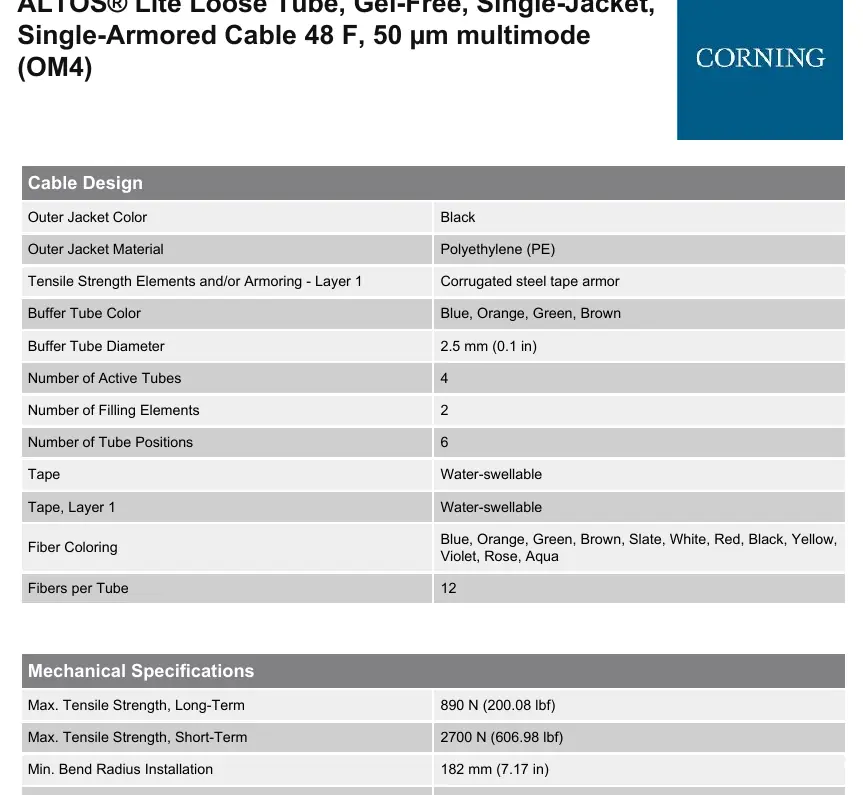
Cable Design
The cable construction consists of the following elements:
- Central Element: Dielectric
- Armor: Corrugated steel tape
- Outer Jacket: Black Polyethylene (PE)
- Buffer Tubes: 4 active tubes, 2 filling elements
- Fiber Count: 48 fibers
- Ripcord: 2 ripcords included for easy stripping
Optical Characteristics
The cable is optimized for multimode applications:
- Fiber Type: Multimode (OM4)
- Wavelengths: 850 nm / 1300 nm
- Maximum Attenuation: 3.0 dB/km / 1.0 dB/km
- Minimum Effective Modal Bandwidth (EMB): 4700 MHz*km
Safety and Compliance
The cable is RoHS compliant (2011/65/EU). For indoor applications, it must be installed in accordance with National Electrical Code (NEC) Article 770. For further support, contact Corning Optical Communications LLC at 800-743-2675 or visit www.corning.com/opcomm.
Official resources from the manual
Manufacturer information
Corning Optical Communications
Practical help
Common problems
Fiber damage during installation
Ensure the cable is not bent beyond the minimum installation bend radius of 182 mm.
Installation failure due to temperature
Ensure the ambient temperature is at -30 °C during installation. Store the cable in a temperature-controlled environment before use.
Excessive tension during pulling
Do not exceed the short-term maximum tensile strength of 2700 N during installation.
Before use
- Verify the installation environment temperature is -30 °C.
- Ensure the installation path allows for a minimum bend radius of 182 mm.
- Confirm the application (aerial, duct, or direct-buried) is compatible with the cable specifications.
- Check that the cable is stored in a proper temperature environment before deployment.
Specs in practice
- Min. Bend Radius
- The minimum radius the cable can be bent without damaging the fibers or the structure.
- Max. Tensile Strength
- The maximum pulling force the cable can withstand during installation (short-term) or while in service (long-term).
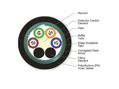
Images and diagrams
- The cross-section diagram illustrates the internal structure, including the central dielectric element, buffer tubes, water-swellable tape, corrugated steel armor, and the outer polyethylene jacket.
- The diagram highlights the location of the ripcords, which are essential for easy stripping of the outer jacket.
Model compatibility
- Suitable for indoor use only when installed according to National Electrical Code (NEC) Article 770.
- Designed for campus backbones and outdoor installations including aerial, duct, and direct-buried.

Manual page author
Emily Carter
User documentation editor
Prepares concise manual descriptions and highlights the most useful setup, operation, and maintenance information for readers.