General / Accessories
Corning MIC Tight-Buffered Plenum Cable Specification Guide
Technical specification guide for Corning MIC Tight-Buffered Plenum cables (2-24 fibers). Includes environmental temperature ranges, mechanical characteristics, transmission performance data, and ordering information.
Table of contents
Manual images
Jump to the sectionQuick guide from the manual
This document provides technical specifications for Corning MIC Tight-Buffered Plenum cables, available in 2-24 fiber configurations. It is intended for network engineers and installers to verify environmental requirements, mechanical limits, and transmission performance for specific network deployments. Always ensure the cable is stored in a proper temperature environment prior to installation to achieve optimal results.
Product overview
Corning MIC plenum cables are designed for use in plenum, riser, and general building environments for intrabuilding backbone and horizontal installations. Key features include:
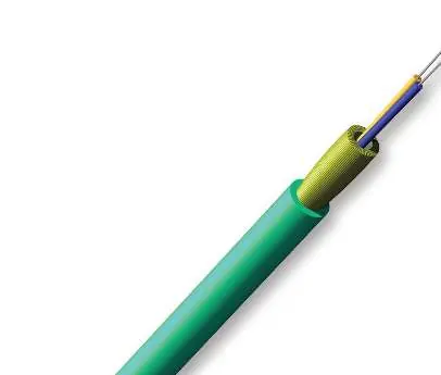
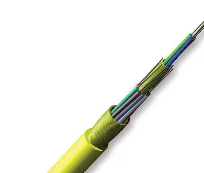
- 900 µm buffered fibers: Designed for easy, consistent stripping and termination.
- All-dielectric construction: Requires no grounding or bonding.
- Flame-retardant jacket: Provides rugged protection.
- Visual identification: Available in 12 standard jacket colors (blue, orange, green, brown, slate, white, red, black, yellow, violet, rose, and aqua).
Temperature and mechanical specifications
Adherence to temperature and mechanical limits is critical for cable integrity:
- Storage Temperature: -40 °C to 70 °C (-40 °F to 158 °F).
- Installation Temperature: 0 °C to 60 °C (32 °F to 140 °F).
- Operation Temperature: 0 °C to 70 °C (32 °F to 158 °F).
The manual provides detailed tables for mechanical characteristics, including maximum tensile strength (short-term and long-term) and minimum bend radius requirements for both installation and operation phases. These values vary based on the fiber count (e.g., 2, 4, 6, 8, 12, 18, 24 fibers).
Transmission performance
The guide includes comprehensive transmission performance tables for both Multimode (OM1, OM2, OM3, OM4, OM4 Extended Distance) and Single-mode (SMF-28e, SMF-28 Ultra) fibers. These tables detail:
- Fiber core diameter (µm)
- Wavelengths (nm)
- Maximum attenuation (dB/km)
- Serial Gigabit Ethernet distances
- Bandwidth specifications (OFL and EMB)
Ordering information
The cable part numbers are determined by a specific code structure. Users can select fiber count, fiber code, cable type, jacket type, fiber placement, markings, tensile strength, performance option code, and special requirements. For custom color options or additional information, contact Corning Customer Care at 1-800-743-2675.
Manufacturer information
Corning Optical Communications
Practical help
Common problems
Cable identification
Use the 12 standard jacket colors (blue, orange, green, brown, slate, white, red, black, yellow, violet, rose, aqua) for easy visual identification.
Grounding requirements
No grounding or bonding is required due to the all-dielectric cable construction.
Before use
- Verify the installation environment temperature is between 0 °C and 60 °C.
- Ensure the cable has been stored in a proper temperature environment (-40 °C to 70 °C) prior to installation.
- Check the specific fiber count and type against your network requirements.
- Verify the minimum bend radius for installation (varies by fiber count) to prevent fiber damage.
- Confirm the maximum tensile strength limits for your installation method.
Specs in practice
- Min. Bend Radius (Installation)
- The minimum radius the cable can be bent during the installation process without damaging the fibers.
- Min. Bend Radius (Operation)
- The minimum radius the cable can be bent once installed and in service.
- Max. Tensile Strength (Short-Term)
- The maximum pulling force allowed during the installation process.
Images and diagrams
- The cable construction consists of a flame-retardant outer jacket, dielectric strength members, and tight-buffered fibers.
- The structure is all-dielectric, meaning it contains no metallic components.
Model compatibility
- Meets NEC OFNP and FT-6 listing requirements.
- Suitable for plenum, riser, and general building applications.
- 50 µm multimode fiber (OM3/OM4/OM4+) meets 0.75 ns optical skew when used in Corning Plug and Play/EDGE systems.

Manual page author
Emily Carter
User documentation editor
Prepares concise manual descriptions and highlights the most useful setup, operation, and maintenance information for readers.