General / Accessories
Corning MIC Unitized Tight-Buffered Cable Specification Sheet
Quick guide to Corning MIC Unitized Tight-Buffered Cables (36-144 fibers). Includes technical specifications, temperature ranges, mechanical characteristics, and ordering information.
Table of contents
Manual images
Jump to the sectionQuick guide from the manual
This document provides technical specifications and ordering information for Corning MIC Unitized Tight-Buffered Cables, designed for riser and general-purpose intrabuilding backbone installations. These cables feature 900 µm buffered fibers, all-dielectric construction, and flame-retardant jackets.
Product Overview
The MIC Unitized Riser Cables are designed for easy, consistent stripping and termination. Key features include:
- All-dielectric construction: Requires no grounding or bonding.
- Flame-retardant jacket: Provides rugged durability.
- Identification: 6-, 12-, or 24-fiber subunits allow for quick identification.
- Standards compliance: Meets National Electrical Code (NEC) Article 770 and ICEA S-83-596 test criteria; OFNR and FT-4 listed.
Technical Specifications
Ensure the installation environment meets the following requirements:
- Storage Temperature: -40 °C to 70 °C (-40 °F to 158 °F)
- Installation Temperature: -10 °C to 60 °C (14 °F to 140 °F)
- Operation Temperature: -20 °C to 70 °C (-4 °F to 158 °F)
Mechanical Characteristics:
- Max. Tensile Strength (Long-Term): 89 lbf (400 N)
- Max. Tensile Strength (Short-Term): 1320 N (300 lbf)
Refer to the tables in the full document for specific bend radius and weight data based on fiber count (36, 48, 60, 72, 96, or 144 fibers).
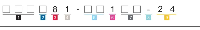
Ordering Information
The cable part number is determined by a specific code structure. You must select the fiber count, fiber code, cable type, jacket type, subunit fiber count, tensile strength, performance option code, and special requirements. Contact Corning Customer Care at 1-800-743-2675 for assistance with ordering specific configurations.
Manufacturer information
Corning Optical Communications
Practical help
Common problems
Cable temperature outside of installation range
Store the cable in a proper temperature environment prior to installation to allow the cable temperature to reach the specified installation range (-10 °C to 60 °C).
Difficulty identifying cable configuration
Use the Ordering Information section on page 4 to decode the part number based on fiber count, fiber type, and performance options.
Before use
- Verify the fiber count (36-144) matches your project requirements.
- Ensure the installation environment is within the specified temperature range (-10 °C to 60 °C).
- Check the minimum bend radius for your specific fiber count during installation.
- Confirm the cable type (Riser) is appropriate for your building application.
- Ensure the cable is not subjected to tensile forces exceeding the short-term limit (1320 N) during installation.
Specs in practice
- Min. Bend Radius (Installation)
- The minimum radius the cable can be bent during installation without causing damage to the fibers.
- All-dielectric
- The cable contains no metallic components, eliminating the need for grounding or bonding.
Images and diagrams
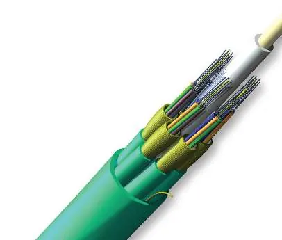
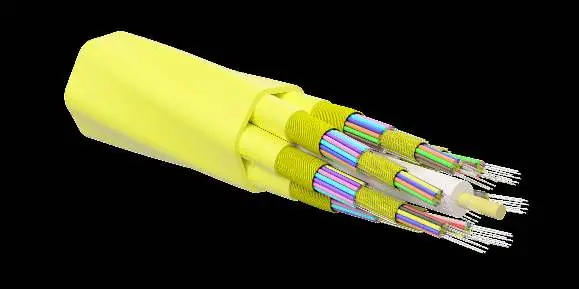
- The cross-section diagram illustrates the internal components: Ripcord, Dielectric Strength Members, Dielectric Central Element, Tight-Buffered Fiber, Subunit Jacket, and Flame-Retardant Outer Jacket.
Model compatibility
- Compatible with standard riser and general building backbone installations.
- Meets NEC Article 770 and ICEA S-83-596 requirements.

Manual page author
Michael Turner
Technical manual editor
Reviews PDF manuals for structure, safety notes, and practical product details so readers can find the right information quickly.