Electronics / Cables & Adapters
Corning MIC Tight-Buffered Cable User Guide
Quick guide for the Corning MIC Tight-Buffered Cable (2-fiber, 50 µm OM3). Includes installation requirements, environmental conditions, and technical specifications.
Table of contents
Manual images
Click an image to enlargeQuick guide from the manual
The Corning MIC Tight-Buffered Cable is designed for indoor use in riser and general-purpose environments, including intrabuilding backbones and horizontal installations. This cable features an all-dielectric construction, meaning it requires no grounding or bonding. It is rated as OFNR and FT-4, making it suitable for riser shafts and telecommunications rooms.
Product Overview
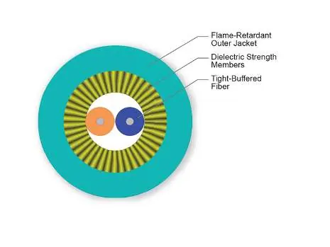
The cable utilizes 900 µm buffered fibers, which allow for easy and consistent stripping during termination. The fibers are protected by dielectric strength members and a flame-retardant outer jacket. The specific model 002T81-31180-24 contains 2 fibers with 50 µm multimode (OM3) characteristics.
Installation and Environmental Conditions
To ensure the integrity of the fiber optic cable, adhere to the following environmental limits:
- Installation Temperature: -10 °C to 60 °C (14 °F to 140 °F)
- Operation Temperature: -20 °C to 70 °C (-4 °F to 158 °F)
- Storage Temperature: -40 °C to 70 °C (-40 °F to 158 °F)
Bend Radius Requirements:
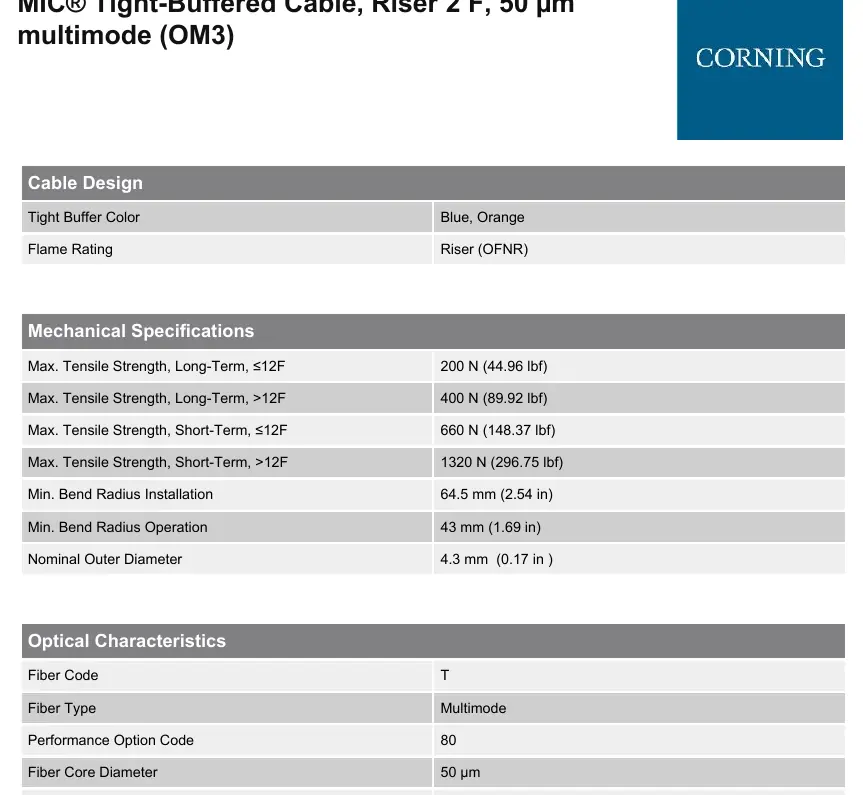
- Installation: Minimum 64.5 mm (2.54 in)
- Operation: Minimum 43 mm (1.69 in)
Technical Specifications
The cable is designed for high-performance networking with the following key parameters:
- Fiber Count: 2
- Fiber Category: 50 µm MM (OM3)
- Wavelengths: 850 nm / 1300 nm
- Maximum Attenuation: 2.8 dB/km (850 nm) / 1.0 dB/km (1300 nm)
- Tensile Strength (Long-Term, ≤12F): 200 N (44.96 lbf)
- Tensile Strength (Short-Term, ≤12F): 660 N (148.37 lbf)
Standards and Compliance
This cable meets the application requirements of the National Electrical Code (NEC) Article 770 and ICEA S-83-596 test criteria. It is compliant with RoHS 2011/65/EU and meets UL-1666 and CSA FT-4 flame test standards.
Manufacturer information
Corning Optical Communications
Practical help
Common problems
Signal loss due to excessive bending
Ensure the cable is not bent tighter than the minimum radius: 64.5 mm during installation and 43 mm during operation.
Fiber damage during pulling
Do not exceed the maximum short-term tensile strength of 660 N for this cable configuration.
Before use
- Verify the part number is 002T81-31180-24.
- Confirm the environment is indoor-only.
- Ensure the installation area temperature is between -10 °C and 60 °C.
- Check that the cable path allows for the minimum bend radius of 64.5 mm.
Specs in practice
- All-dielectric
- The cable contains no metal, so no grounding or bonding is required.
- Tight-Buffered
- 900 µm fiber coating that allows for easier stripping and termination compared to loose-tube designs.
Images and diagrams
- The cross-section diagram illustrates the internal structure: the central fibers are surrounded by dielectric strength members, all encased in a flame-retardant outer jacket.
Model compatibility
- Designed for intrabuilding backbone and horizontal installations.
- Meets NEC Article 770 and ICEA S-83-596 standards.

Manual page author
Emily Carter
User documentation editor
Prepares concise manual descriptions and highlights the most useful setup, operation, and maintenance information for readers.