Computers / PC Components
User Manual for Corsair 110R Mid-Tower Gaming Case
Quick guide for the Corsair 110R Mid-Tower Gaming Case. Includes installation steps for motherboard, storage, PSU, PCI-e cards, and front I/O wiring, plus technical specifications and compatibility details.
Table of contents
Manual images
Click an image to enlargeQuick guide from the manual
This document provides essential installation and setup instructions for the Corsair 110R Mid-Tower Gaming Case. It covers component compatibility, accessory identification, and step-by-step installation procedures for your PC build.
Case Specifications
Before beginning your build, ensure your components fit within the following limits:
- Maximum GPU Length: 330mm
- Maximum CPU Cooler Height: 160mm
- Maximum PSU Length: 180mm
- Motherboard Compatibility: ATX, MATX, ITX
Fan and Radiator Support
- Front: 3 x 120mm / 2 x 140mm fans; 360mm / 280mm radiator
- Top: 1 x 120mm / 1 x 140mm fans; 140mm / 120mm radiator
- Rear: 1 x 120mm fan; 120mm radiator
Accessory Kit Contents
The accessory kit includes the following hardware:
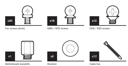
- Fan screws (short): x20
- MBD / HDD screws: x18
- ODD / SSD screws: x12
- Motherboard standoffs: x1
- Washers: x8
- Cable ties: x12
Installation Procedures
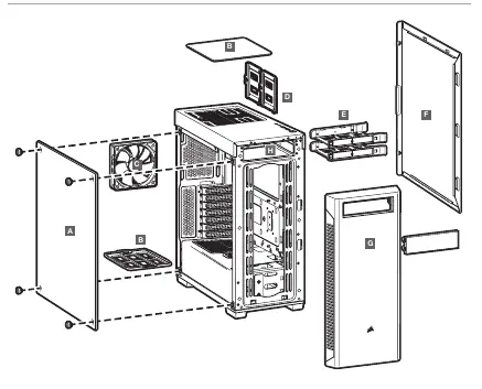
Removing Side Panels
To access the interior, remove the thumbscrews securing the side panels and slide them off the chassis.
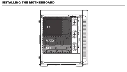
Installing the Motherboard
Align your motherboard (ATX, MATX, or ITX) with the standoffs inside the case and secure it using the appropriate screws from the accessory kit.
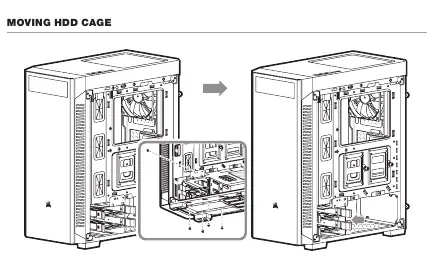
Installing Storage (HDDs and SSDs)
HDDs: Slide the hard drive into the HDD tray and secure it. The HDD cage can be moved if necessary for better cable management or radiator clearance.
SSDs: Mount SSDs onto the provided SSD trays and attach them to the designated mounting points on the chassis.
Installing the PSU
Slide the power supply unit into the bottom rear of the case and secure it from the back with screws.
Installing PCI-e Cards
Remove the necessary expansion slot covers on the back of the case, insert your PCI-e card (e.g., GPU), and secure it with screws.
Installing Front I/O Connectors
Connect the front panel cables to your motherboard headers. The connectors include:
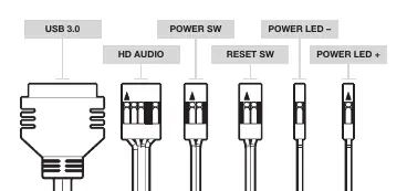
- USB 3.0
- HD Audio
- Reset SW
- Power SW
- Power LED + / Power LED -
Note: Polarity does not matter for the Power and Reset headers, but it is critical for the LED headers.
Frequently Asked Questions
- Does polarity matter for the I/O panel? No, only for the LED headers.
- What if parts are damaged? Visit support.corsair.com to request an RMA for replacement parts.
Official resources from the manual
Manufacturer information
Corsair Memory, Inc.
Practical help
Common problems
Damaged case or non-working fan
Visit support.corsair.com and request an RMA to have the damaged parts replaced.
Polarity of I/O connectors
Polarity does not matter for power and reset headers; it only matters for LED headers.
Before use
- Verify all screws and standoffs are present in the accessory kit.
- Ensure your motherboard form factor is compatible (ITX, MATX, ATX).
- Check GPU length (max 330mm) and CPU cooler height (max 160mm).
- Confirm PSU length (max 180mm).
Specs in practice
- Max GPU Length
- Maximum length of graphics card supported: 330mm.
- Max CPU Height
- Maximum height of CPU cooler supported: 160mm.
- Max PSU Length
- Maximum length of power supply supported: 180mm.
Images and diagrams
- The manual includes a detailed wiring diagram for front I/O connectors (USB 3.0, HD Audio, Reset SW, Power SW, Power LEDs).
- The accessory kit diagram identifies specific screws for fans, motherboard/HDD, and ODD/SSD.
Model compatibility
- Supports ATX, MATX, and ITX motherboards.
- Front radiator support: 360mm / 280mm.
- Top radiator support: 140mm / 120mm.

Manual page author
David Miller
Documentation analyst
Organizes user manual content into clear summaries, with attention to model details, product context, and everyday usability.