Computers / Cooling Systems
Alphacool Core 11x 3-Pin DRGB Splitter User Guide
Quick guide for the Alphacool Core 11x 3-Pin DRGB Splitter. Learn how to mount the controller, connect your aRGB strips, and safely power the device using SATA.
Table of contents
Manual images
Click an image to enlargeQuick guide from the manual
The Alphacool Core 11x 3-Pin DRGB Splitter allows you to expand your aRGB lighting setup. This device requires a 3-pin aRGB header on your motherboard; it is not compatible with 4-pin headers. Ensure your computer is completely powered off and unplugged before installation to prevent electrical damage.
Mounting the Controller
The controller can be mounted inside your computer case using the included adhesive tape and velcro fastener.
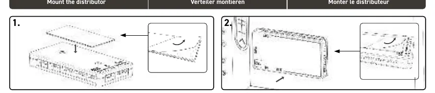
- Remove the upper protective film from the adhesive tape and stick it to the bottom of the controller.
- Remove the second protective film and press the controller firmly onto the computer case.
- The velcro layer allows you to detach the controller from the case if needed.
Connecting the Cables
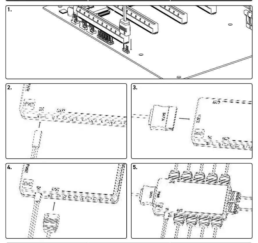
- Motherboard Connection: Connect the 2-pin aRGB cable to your motherboard's aRGB output. Ensure the header is a 3-pin terminal.
- Controller Input: Connect the 2-pin aRGB IN plug to the controller.
- Power Connection: Connect the SATA power plug from your power supply unit to the PWR input on the controller. Ensure the power supply is switched off during this process.
- aRGB Strips: Connect your aRGB strips to the OUT sockets on the controller.
Technical Specifications and Limitations
- Maximum Capacity: You can connect up to 11 aRGB strips.
- Power Limit: The total power consumption of all connected strips must not exceed 22.5W (4.5A).
Safety Warnings
The computer power switch does not cut off power to the internal components. You must unplug the power cord from the wall socket before opening the computer chassis to perform any installation work.
Practical help
Common problems
Motherboard aRGB header is 4-pin
Do not connect. The controller requires a 3-pin aRGB header. Connecting to a 4-pin header may cause damage.
Controller not powering on
Ensure the SATA power cable from your power supply is securely connected to the PWR input on the controller.
Before use
- Ensure the computer is turned off and unplugged from the wall socket.
- Verify your motherboard has a 3-pin aRGB header.
- Prepare the adhesive tape or velcro for mounting.
- Check that your total aRGB strip power consumption is under 22.5W.
Images and diagrams
- The controller features an IN port for the motherboard signal and multiple OUT ports for aRGB strips.
- The PWR port is dedicated to SATA power input.
Model compatibility
- Compatible with 3-pin aRGB headers only.
- Not compatible with 4-pin RGB headers.

Manual page author
Emily Carter
User documentation editor
Prepares concise manual descriptions and highlights the most useful setup, operation, and maintenance information for readers.