Computers / Storage
Installation Guide for Corsair Carbide Series 100R Silent Edition PC Case
Quick installation guide for the Corsair Carbide Series 100R Silent Edition mid-tower PC case. Includes setup steps for motherboard, PSU, drives, and fans.
Table of contents
Manual images
Click an image to enlargeQuick guide from the manual
The Corsair Carbide Series 100R Silent Edition is a mid-tower PC case designed for professional environments with tool-free installation options. This guide covers the essential steps to build your system.
Case Specifications
- Dimensions: 471mm (L) x 200mm (W) x 430mm (H)
- Weight: 4.9kg
- Max GPU Length: 414mm (top slots), 275mm (lower slots)
- Max CPU Cooler Height: 150mm
- Max PSU Length: 260mm
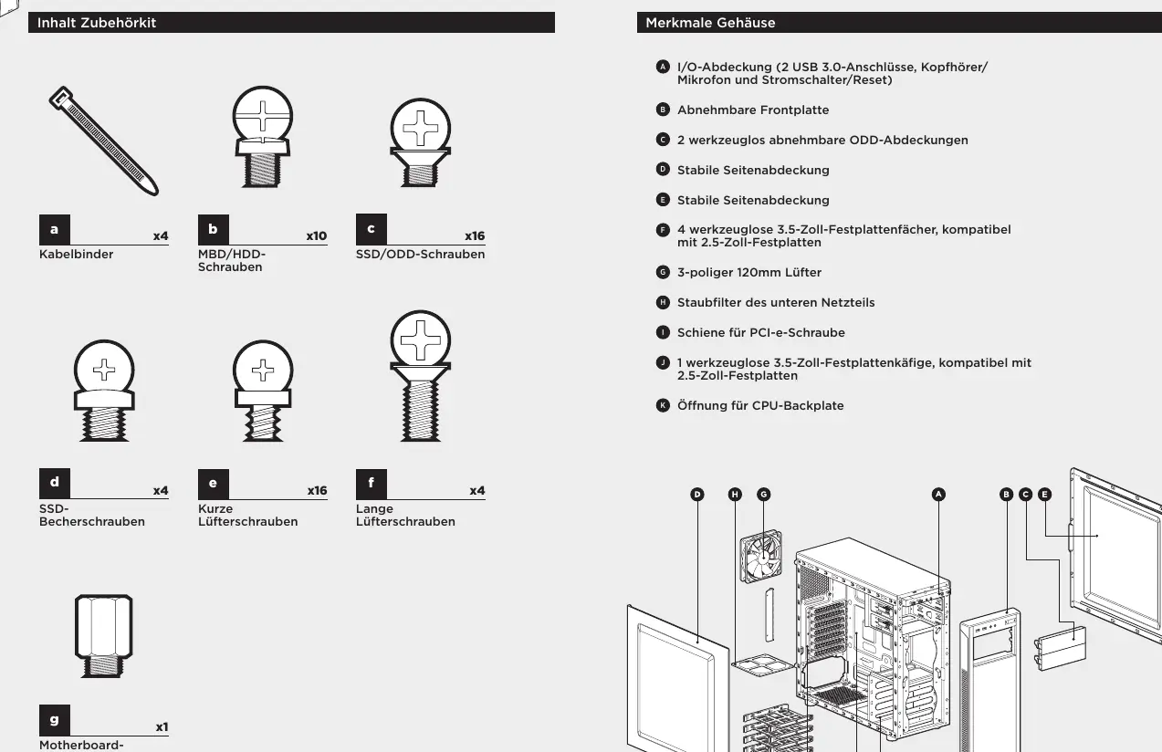
Accessory Kit Contents
Ensure you have the following components before starting:
- Cable ties (x4)
- Motherboard standoffs (x1)
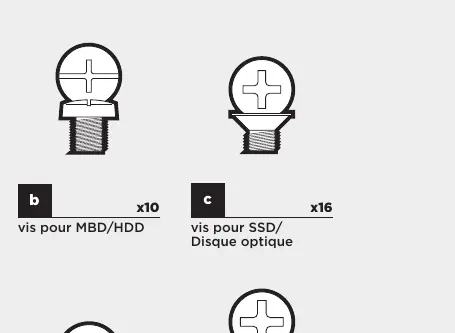
- SSD pan head screws (x4)
- Short fan screws (x16)
- Long fan screws (x4)
- MBD/HDD screws (x10)
- SSD/ODD screws (x16)
Installation Steps
1. Removing the Side Panels
Remove the thumbscrews and slide the side panels back and out. Corsair recommends removing both panels during system assembly to avoid damage.
2. Installing the Motherboard
Install your motherboard's I/O shield first. Align the motherboard with the pre-installed standoffs and secure it using the provided MBD screws.
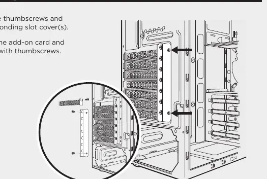
3. Installing PCI-e/PCI Cards
Remove the thumbscrews and the corresponding slot covers. Insert your add-on card and secure it with the thumbscrews.
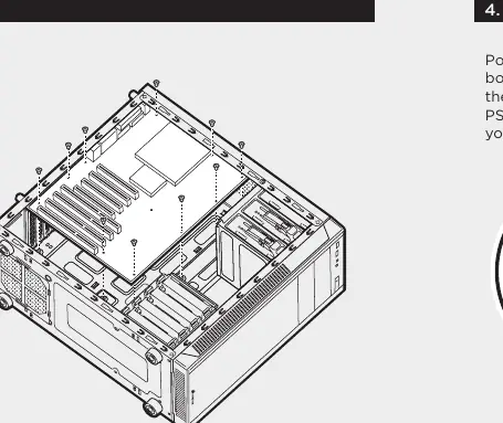
4. Installing the PSU
Position the power supply unit at the bottom of the case, align it with the case holes, and secure it with the screws provided with your power supply.
5. Removing the Front Fascia
Grasp the tab located at the bottom of the front panel and pull outward.
6. Installing an ODD
Remove the 5.25" drive bay cover from the front panel. Slide the optical drive into the bay until the tool-free latch clicks.
7. Installing SSDs and HDDs
The drive trays support both 3.5" and 2.5" devices. For 3.5" HDDs, pull the tray sides to extend mounting points, place the drive, and push back to close. For 2.5" SSDs, place the drive on the tray and secure with the provided SSD screws.
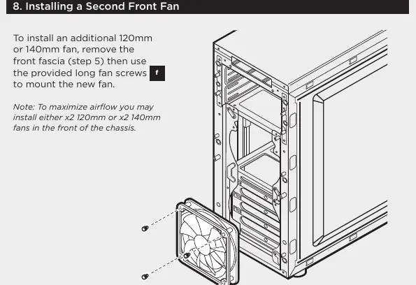
8. Installing a Second Front Fan
Remove the front fascia, then use the provided long fan screws to mount an additional 120mm or 140mm fan.
9. Powering the Case Fans
Connect the SATA power connector to the PSU SATA cable. Connect the 3 or 4-pin fan connector to the case fan header. Use the fan speed selector button on the case to toggle speeds.
10. Installing Front I/O Connectors
Refer to your motherboard manual for the correct locations and pin-outs for the USB 3.0, HD Audio, Power SW, Reset SW, and Power LED connectors.
Frequently Asked Questions
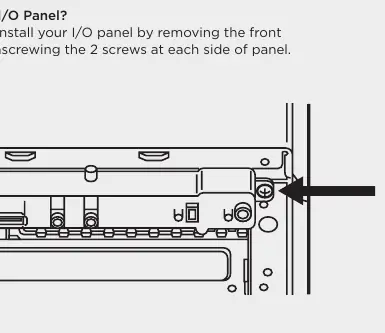
- Removing I/O Panel: Remove the front fascia, then unscrew the 2 screws on each side of the panel.
- Polarity: Only LED headers require specific polarity; power and reset headers do not.
- Damaged Parts: Visit support.corsair.com to request an RMA for damaged parts or faulty fans.
Official resources from the manual
Manufacturer information
Corsair Memory, Inc.
Practical help
Common problems
Case received damaged or fan not working
Visit support.corsair.com and request an RMA to replace the damaged part.
Difficulty removing I/O panel
Remove the front fascia first, then unscrew the two screws on each side of the I/O panel.
Unsure about I/O header polarity
Only the LED headers require specific polarity. Power and reset headers do not.
Before use
- Verify all components fit within case dimensions (GPU length, CPU cooler height, PSU length).
- Install the motherboard I/O shield before mounting the motherboard.
- Ensure all necessary screws are available from the accessory kit.
- Remove both side panels to reduce clutter during assembly.
Specs in practice
- Maximum GPU length (Top slots)
- 414mm
- Maximum GPU length (Lower slots)
- 275mm
- Maximum CPU cooler height
- 150mm
- Maximum PSU length
- 260mm
Images and diagrams
- Fan speed selector: 3-position switch on the case to toggle fan speed.
- Front I/O connectors: USB 3.0, HD Audio, Power SW, Reset SW, Power LED +/-.
Model compatibility
- Supports 3.5" and 2.5" drives.
- Front fan mounts: x2 120mm or x2 140mm.
- Rear fan mount: 120mm.

Manual page author
Michael Turner
Technical manual editor
Reviews PDF manuals for structure, safety notes, and practical product details so readers can find the right information quickly.