Computers / PC Components
User Manual for Thermaltake The Tower 300 PC Case
Quick guide for the Thermaltake The Tower 300 Micro Tower PC case. Includes installation steps for motherboard, PSU, cooling, and storage, along with technical specifications and compatibility limits.
Table of contents
Manual images
Click an image to enlargeQuick guide from the manual
The Thermaltake The Tower 300 is a Micro Tower PC case designed for high-performance builds. Before starting your build, ensure your components fit within the following limits:
- Motherboard Compatibility: ITX or mATX.
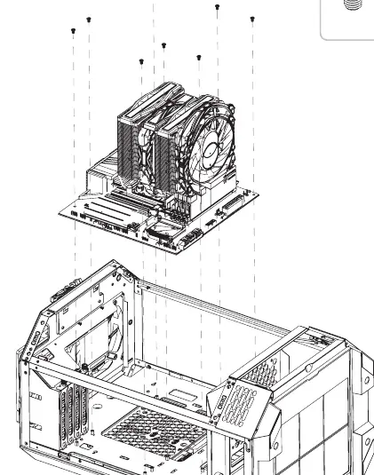
- CPU Cooler Height: Maximum 210 mm.
- VGA Length: Maximum 280 mm (with power cover) or 400 mm (without power cover).
- PSU Length: Maximum 220 mm.
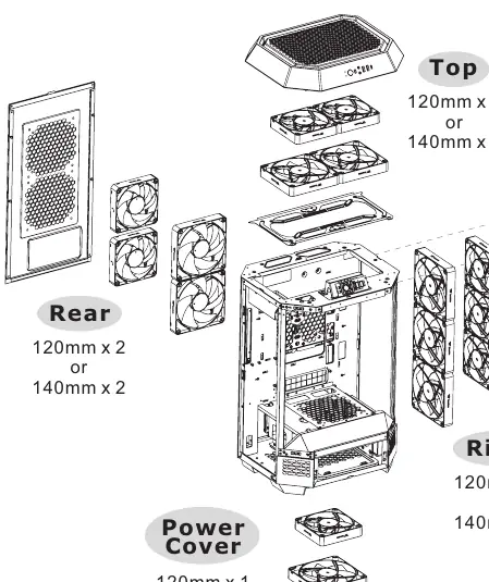
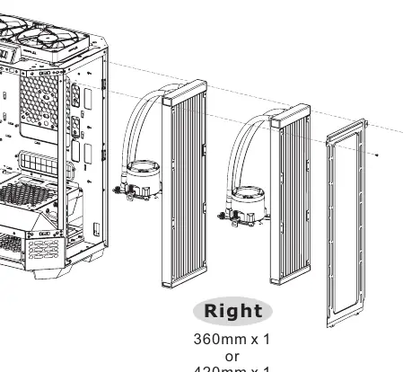
- Radiator Support: Up to 420 mm (Right side).
Installation Guide
Follow these steps to install your components into the chassis:
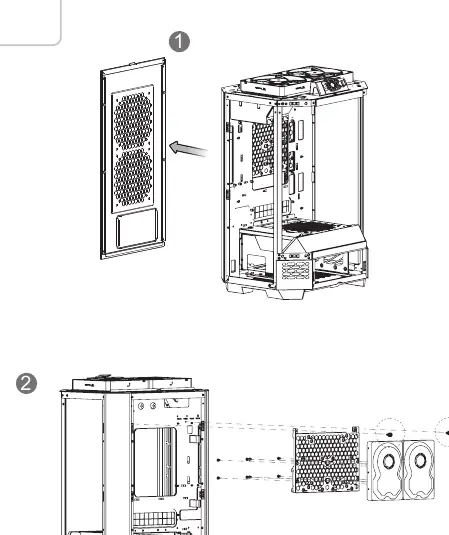
- Remove Components: Start by removing the necessary panels and filters to access the interior.
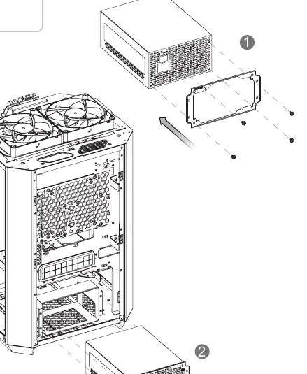
- Power Supply Unit (PSU) Installation: Secure the PSU into the designated area using the provided screws.
- Motherboard Installation: Mount your ITX or mATX motherboard using the appropriate standoffs and screws.
- HDD/SSD Installation: The case supports both 3.5" and 2.5" drives. Mount them in the designated drive bays using the provided screws.
- VGA Card Installation: Install your graphics card into the PCIe slot. Ensure you have removed the necessary expansion slot covers.
- Air Cooling Installation: Install fans on the top, rear, right side, or power cover as needed.
- AIO Liquid Cooling Installation: Mount the radiator on the right side of the case.
I/O Connection
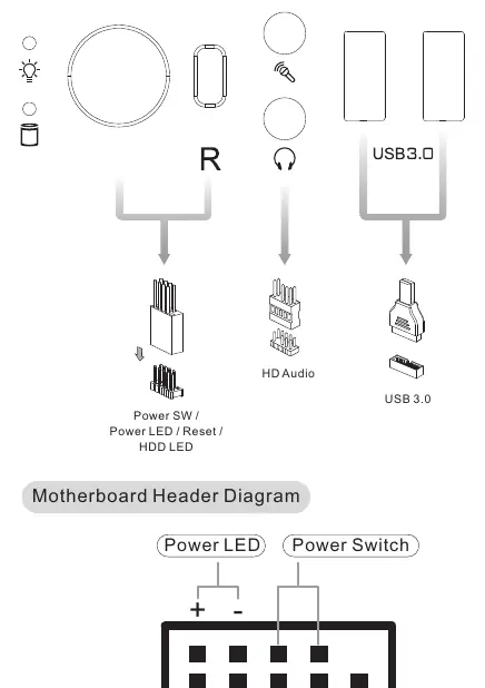
Connect the front panel cables to the corresponding headers on your motherboard. Refer to your motherboard manual for the exact pinout. The case includes connectors for Power SW, Power LED, Reset, HDD LED, and HD Audio, as well as USB 3.0 and Type-C headers.
Maintenance
To maintain optimal airflow and prevent dust buildup, regularly remove and clean the dust filters. The filters are located on various panels of the chassis and can be removed by sliding or pulling them out as indicated in the assembly diagrams.
Manufacturer information
Thermaltake
Practical help
Common problems
Graphics card does not fit
Check if the power cover is installed. Removing the power cover increases maximum VGA length from 280 mm to 400 mm.
CPU cooler is too tall
Ensure your CPU cooler height does not exceed 210 mm.
PSU does not fit
Ensure your power supply unit length is within the 220 mm limit.
Before use
- Verify motherboard form factor is ITX or mATX.
- Check CPU cooler height against the 210 mm limit.
- Check VGA card length against the 280 mm/400 mm limit.
- Ensure PSU length is under 220 mm.
- Identify all necessary screws and standoffs from the accessory list.
Specs in practice
- VGA length limit
- Maximum length of the graphics card supported. 280 mm with power cover, 400 mm without.
- CPU cooler height
- Maximum vertical clearance for air coolers, limited to 210 mm.
Images and diagrams
- The I/O connection diagram shows the pinout for the front panel headers (Power SW, Reset, HDD LED, Power LED).
- The cooling diagrams illustrate fan placement options for top, rear, right, and power cover positions.
Model compatibility
- Supports ITX and mATX motherboards only.
- Right side radiator support up to 420 mm.

Manual page author
Michael Turner
Technical manual editor
Reviews PDF manuals for structure, safety notes, and practical product details so readers can find the right information quickly.