Home / Garage Door Openers
Craftsman 139.53962SRT Garage Door Opener Owner's Manual
Comprehensive owner's manual for the Craftsman 139.53962SRT garage door opener. Includes detailed assembly, installation, adjustment, operation, and troubleshooting instructions.
Table of contents
Manual images
Click an image to enlargeQuick guide from the manual
This manual provides instructions for the assembly, installation, and maintenance of the Craftsman 139.53962SRT garage door opener. Before beginning, ensure your garage door is properly balanced and lubricated. Remove all ropes and disable existing locks on the door. The opener requires a 120V 60Hz power source. Always follow safety precautions, as garage doors are under extreme tension and can cause serious injury.
Assembly
The assembly process involves preparing the rail and trolley system:
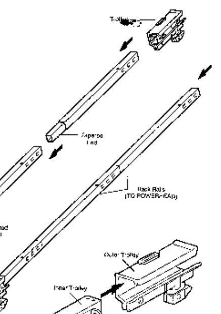
- Rail and Trolley: Assemble the rail sections and install the inner/outer trolley. Ensure the wear pads are in place.
- Idler Pulley: Install the idler pulley into the front rail window.
- Chain/Cable: Route the chain and cable around the idler pulley and sprocket, ensuring it is not twisted.
- Tension: Tighten the chain until it is approximately 1/2 inch above the base of the rail at its midpoint.
Installation
Installation steps include:
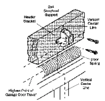
- Header Bracket: Determine the location (wall or ceiling) and fasten securely to structural supports.
- Opener Mounting: Position the opener and hang it using the provided hanging brackets.
- Door Control: Install the control console at least 5 feet above the floor, out of reach of children.
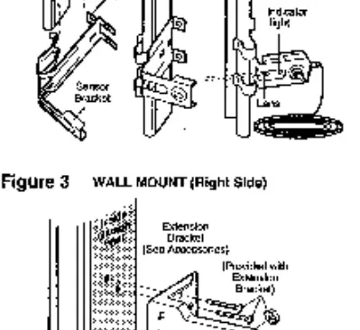
- Safety Sensors: Install the safety reversing sensors 4-6 inches above the floor. The sending and receiving eyes must face each other.
- Emergency Release: Attach the red emergency release rope and handle.
Adjustment
Proper adjustment is critical for safety:
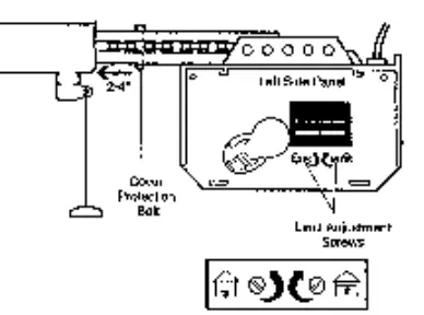
- Travel Limits: Adjust the UP and DOWN limit screws to set the stopping points for the door.
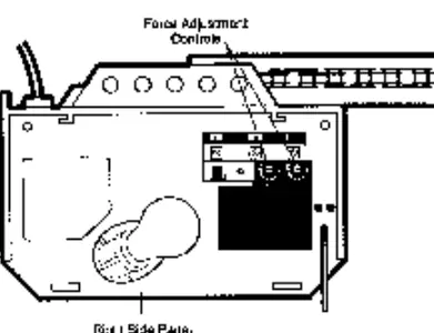
- Force Adjustments: Set the force controls to ensure the door stops or reverses if it encounters an obstruction.
- Safety Reverse Test: Place a one-inch board on the floor and operate the door. It must reverse upon striking the object.
Operation
The opener can be activated via remote control or the wall-mounted door control. The system includes a safety reverse feature that stops and reverses the door if the safety sensor beam is obstructed while closing.
Maintenance
- Monthly: Manually operate the door to check for binding or imbalance. Repeat the safety reverse test.
- Twice a Year: Check chain tension.
- Yearly: Oil door rollers, bearings, and hinges.
Troubleshooting
If the opener fails to operate, check the power supply and circuit breaker. If the door reverses for no apparent reason, check for obstructions, ensure sensors are aligned, and verify force settings. If the motor hums but does not move, check for broken springs or a locked door.
Manufacturer information
CRAFTSMAN
Practical help
Common problems
Opener does not operate from door control or remote
Check power supply, fuse box, or circuit breaker. Ensure the door is not frozen to the ground or locked.
Door reverses for no apparent reason
Check for obstructions, ensure safety sensors are aligned, and verify force settings.
Remote control has short range
Change the location of the remote in the car or ensure the antenna on the opener extends fully downward.
Opener motor hums but won't work
Check for broken garage door springs or a locked door.
Before use
- Ensure the garage door is properly balanced and lubricated.
- Remove all ropes connected to the garage door.
- Disable all existing door locks.
- Verify 120V 60Hz power supply.
- Ensure the door control is mounted at least 5 feet above the floor.
Specs in practice
- Safety Sensor Height
- Must be installed 4-6 inches above the garage floor.
Images and diagrams
- Assembly diagrams show rail, trolley, and chain routing.
- Installation diagrams illustrate header bracket mounting and safety sensor placement.
- Adjustment diagrams identify the location of limit and force adjustment screws on the side panels.
Model compatibility
- Compatible with sectional and one-piece garage doors.
- Requires reinforcement for lightweight doors (fiberglass, aluminum, etc.).

Manual page author
David Miller
Documentation analyst
Organizes user manual content into clear summaries, with attention to model details, product context, and everyday usability.