HVAC / Packaged Rooftop Units
Installation and Use Manual for Air Source Heat Pump Unit
Comprehensive installation and operation guide for the Air Source Heat Pump Unit. Includes wiring instructions, control panel operation, maintenance schedules, and troubleshooting fault codes.
Quick answers from the manual
Quick answer
- The air source heat pump unit is an outdoor heating device. Installation requires a 220V/50Hz power supply with leakage protection, reliable grounding (≤0.1Ω), and proper ventilation. Operation is managed via the wire controller, which supports heating, cooling, and automatic modes. p. 2, 3, 7, 8
First start
- Ensure the unit is level and properly grounded. p. 2, 5
- Fill the pool to 60%-80% capacity before starting. p. 6
Technical specifications
| Parameter | Value | Meaning | Pages |
|---|---|---|---|
| Power Supply | 220V/50Hz | Standard operating voltage | p. 7 |
| Grounding Resistance | ≤0.1Ω | Maximum allowable resistance for safety | p. 2, 8 |
Where to find it in the PDF
- Introduction and Safety p. 1, 2
- Installation Requirements p. 2, 3, 6, 7
- Operation and Control p. 8, 9, 10, 11
- Fault Codes p. 5
Table of contents
Manual images
Click an image to enlargeQuick guide from the manual
This manual provides essential instructions for the installation, operation, and maintenance of the air source heat pump unit. Key requirements include professional installation, proper electrical grounding (resistance ≤0.1Ω), and ensuring adequate ventilation. Always disconnect the power supply before performing any maintenance.
Product introduction
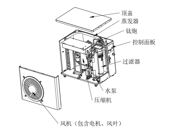
The air source heat pump unit is designed for energy-efficient water heating. It features soft-start technology to protect circuits, ultra-quiet fan blades, and a durable construction with a high-quality copper tube condenser. The unit is designed for outdoor installation in well-ventilated areas.
Installation
The unit must be installed by qualified personnel. Ensure the following conditions are met:
- Environment: Install in a well-ventilated, load-bearing outdoor area away from boiler flues or corrosive environments.
- Electrical: Connect to a 220V/50Hz power supply. Use a leakage protection switch with a capacity greater than the unit's maximum current.
- Grounding: The unit must be reliably grounded (resistance ≤0.1Ω) and equipped with lightning protection.
- Plumbing: Install a water inlet filter and ensure drainage pipes are designed to discharge condensate water.
Operation
The unit is controlled via a wire controller. Key operations include:
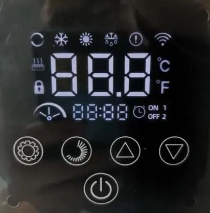
- Mode Selection: Tap the Function key to switch between heating, automatic, and cooling modes.
- Temperature Setting: Use the '+' or '-' keys on the home screen to adjust the set temperature.
- Lock/Unlock: The screen locks automatically after 60 seconds. To unlock, long-press the 'switch' key for 5 seconds until the buzzer beeps.
- Factory Reset: In shutdown state, hold the Switch key + '-' key for 5 seconds to restore factory defaults.
Maintenance
Regular maintenance is crucial for efficiency and longevity:
- Daily: Record operating parameters and check for normal operation (pressure gauge, ventilation, appearance).
- Periodic: Perform weekly, monthly, quarterly, and annual maintenance checks.
- Safety: Always disconnect the main power supply and place a 'no-closing' sign at the switch before inspection.
Troubleshooting
If the unit displays a fault code, refer to the troubleshooting table. Common issues include exhaust temperature faults (E01), water flow switch faults (P01), and high-pressure protection (P02). If problems persist, contact your local agent or service technician.
Practical help
Common problems
E01 - Exhaust temperature fault
Check for system blockages or ventilation issues.
P01 - Water flow switch fault
Verify water flow and ensure the filter is clean.
P02 - High pressure protection
Check for obstructions in the water circuit or airflow.
Unit does not start
Check power supply, leakage protection switch, and ensure the unit is not in a locked state.
Before use
- Verify power supply specifications match the unit nameplate.
- Ensure the leakage protection switch capacity is sufficient.
- Confirm reliable grounding (resistance ≤0.1Ω).
- Check that the water inlet filter is installed.
- Ensure the unit is level and has proper ventilation clearance.
- Remove air from the tubes before initial use.
Specs in practice
- Power Supply
- 220V/50Hz; requires a dedicated circuit with leakage protection.
- Grounding Resistance
- Must be ≤0.1Ω for safe operation.
- Operating Environment
- Outdoor, well-ventilated, load-bearing surface.
Images and diagrams
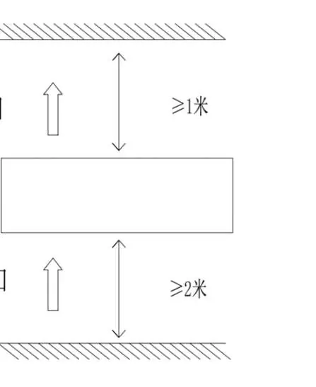
- The installation diagram indicates minimum clearance requirements (≥1m and ≥2m) for proper airflow.
- The exploded view identifies key components: Top Cap, Evaporator, Titanium Cannon, Control Panel, Filter, Pump, and Compressor.
Model compatibility
- Requires professional installation.
- Not for use in areas with corrosive air (e.g., near certain boiler flues).
- Compatible with Tuya APP for remote control.

Manual page author
Michael Turner
Technical manual editor
Reviews PDF manuals for structure, safety notes, and practical product details so readers can find the right information quickly.