Lighting / Controllers & Dimmers
DALI+Push+Phase Cut+0/1-10V LED Dimmer 70160001
Quick installation and wiring guide for the DALI+Push+Phase Cut+0/1-10V LED Dimmer (70160001). This guide covers DIP switch configuration, wiring diagrams for all four dimming modes, safety warnings, and technical specifications.
Table of contents
Manual images
Click an image to enlargeImportant Information
The DALI+Push+Phase Cut+0/1-10V LED Dimmer is a 4-in-1 device designed for versatile LED control. Crucial: You must select the dimming interface using the DIP switch before wiring the device. Do not attempt to wire or use different dimming interfaces simultaneously; only one can be active at a time. Never perform wiring or DIP switch adjustments while the device is powered.
Operation and DIP Switch Settings
Before connecting any control signals, ensure the power is disconnected. Use the DIP switch on the device to select the specific dimming interface required for your control system (DALI, AC Push, 0/1-10V, or Phase Cut). Once the interface is selected, proceed with the appropriate wiring diagram.
Wiring Diagrams
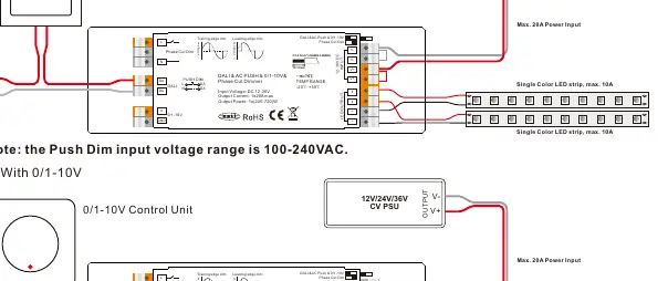
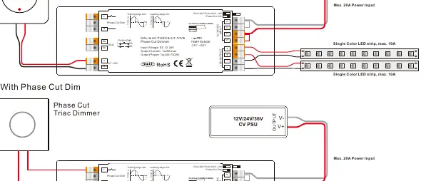
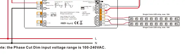
The device supports four distinct wiring configurations based on the control method:
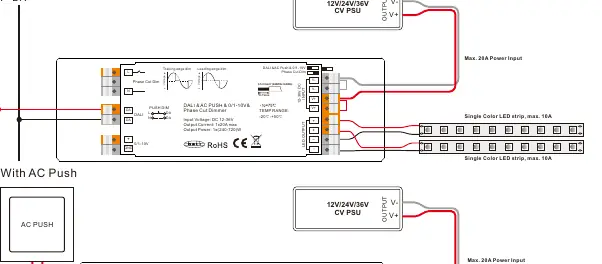
- DALI Bus: Connect the DALI signal to the DA/DA terminals. The DALI address is assigned by the DALI Master controller.
- AC Push: Connect the AC Push signal to the designated input. Note that the Push Dim input voltage range is 100-240VAC.
- 0/1-10V: Connect the 0/1-10V control unit to the 0/1-10V input terminals.
- Phase Cut: Connect the Phase Cut Triac Dimmer to the input. Note that the Phase Cut Dim input voltage range is 100-240VAC.
For all configurations, ensure the wire specifications are 0.5-2.5mm (22AWG-12AWG) and that the rated current of the wire is sufficient for the loads.
Technical Data
- Input Voltage: 12-36V DC
- Output Current: 1x20A max
- Output Power: 1x(240-720)W
- Dimming Range: 0.1%-100%
- Ambient Temperature: -20°C to +50°C
- Waterproof Grade: IP20
- Dimensions: 170 x 53.4 x 28 mm
Safety and Warnings
- Do not select the dimming input while power is applied to the device.
- Do not install the device while power is applied.
- Do not expose the device to moisture.
- Ensure the total load does not exceed 20A.
Practical help
Common problems
Dimming interface not working
Ensure the DIP switch was set before applying power. Different interfaces cannot be used simultaneously.
Device not responding to DALI
Ensure the DALI address is assigned by the DALI Master controller.
Before use
- Verify input voltage is 12-36V DC.
- Ensure the total load does not exceed 20A.
- Select the correct dimming interface using the DIP switch before wiring.
- Ensure wires are 0.5-2.5mm (22AWG-12AWG).
- Confirm the power is OFF before installation.
Specs in practice
- Input Voltage
- 12-36V DC power supply required.
- Output Current
- 1x20A max, suitable for high-power LED strips.
- Waterproof grade
- IP20, suitable for indoor use only.
- Dimming Range
- 0.1%-100% smooth dimming capability.
Images and diagrams
- Wiring diagrams show connections for DALI Bus, AC Push, 0/1-10V, and Phase Cut dimming.
- Terminals support parallel connection for loads.
Model compatibility
- Compatible with universal phase cut dimmers.
- Compatible with DALI DT6 devices.
- Compliant with IEC 62386-101:2014, IEC 62386-102:2014, IEC 62386-207 Ed2.

Manual page author
David Miller
Documentation analyst
Organizes user manual content into clear summaries, with attention to model details, product context, and everyday usability.