Lighting / Fixtures
Rutec LED Dimmer 1-10V 80475
Quick guide for the Rutec LED Dimmer 1-10V (80475). Includes wiring diagrams, technical specifications, installation safety instructions, and operating requirements for this 12/24V DC controller.
Table of contents
Quick guide from the manual
The Rutec LED Dimmer 1-10V (80475) is designed for analog dimming of constant current LED lights in indoor applications. It provides 256 grayscale levels and a dimming range of 0-100%. Please note that this device requires professional installation and specific wiring conditions to function correctly.
Technical Data
- Model: 80475
- Input Voltage: 12/24V DC
- Output: 4x350mA, 4x4.2/8.4W
- Dimensions: 166.0 x 53.4 x 23.0 mm
Installation and Wiring
The device must be installed by a qualified electrician. Ensure the following conditions are met during installation:
- Environment: The controller is not waterproof. If installed outdoors, it must be placed in a waterproof housing. Protect from direct sunlight and rain.
- Ventilation: Install in a location with good ventilation to ensure proper operating temperature.
- Wiring: Verify that the voltage and power adapter are suitable for the controller. Ensure the anode and cathode designations match the controller. Use an appropriate cable cross-section for the connection between the controller and the LED.
- Safety: Never connect cables while the power is on. Check all connections for correctness and potential short circuits before switching on the power.
Safety and Maintenance
- Do not attempt to repair the device yourself, as this will void the manufacturer's warranty.
- Ensure the power supply is disconnected before performing any maintenance or checking connections.
Manufacturer information
rutec Licht GmbH & Co. KG
Practical help
Common problems
Device is not waterproof
If installing outdoors, you must place the controller in a separate waterproof housing.
Overheating
Ensure the device is installed in a location with adequate ventilation to maintain proper operating temperature.
Incorrect polarity
Verify that the anode and cathode designations on your LED setup match the controller's terminals before powering on.
Before use
- Ensure installation is performed by a qualified electrician.
- Verify that the power supply is 12/24V DC.
- Check that the cable cross-section is appropriate for the load.
- Confirm that all connections are secure and free of short circuits.
- Ensure the environment is dry or that a waterproof housing is used.
Specs in practice
- Input 12/24V DC
- The controller requires a stable DC power supply of either 12V or 24V.
- Output 4x350mA
- The device supports four channels of constant current output at 350mA each.
- Dimming Range 0-100%
- Allows full control over light intensity from completely off to full brightness.
Images and diagrams
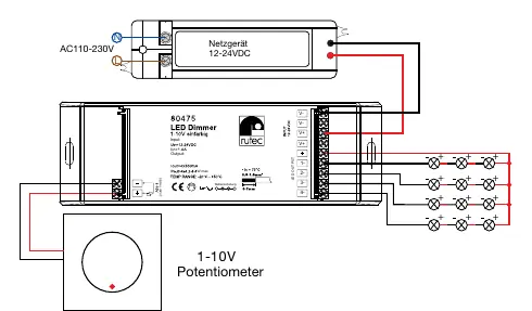
- The wiring diagram shows the connection of the 12-24V DC power supply to the input terminals.
- It illustrates the connection of the 1-10V potentiometer to the signal input.
- It displays the output terminals for connecting the LED lights in a series configuration.

Manual page author
Michael Turner
Technical manual editor
Reviews PDF manuals for structure, safety notes, and practical product details so readers can find the right information quickly.