Lighting / Controllers & Dimmers
User Manual for Sunricher 09.2402K2D.04758 Push Button Single Color DALI Controller
Quick guide for the Sunricher 09.2402K2D.04758 Push Button Single Color DALI Controller. Includes installation steps, wiring diagrams, group configuration, and safety warnings.
Table of contents
Manual images
Click an image to enlargeQuick Guide
The Sunricher 09.2402K2D.04758 is a DALI DT6 push button controller designed for single-color lighting control. It is powered directly by the DALI bus, requiring no additional power supply. The device allows you to control one DALI group from a total of 16 available groups (0-15) using a rotary switch located on the back.
Installation
The device is designed for easy installation using a mounting bracket. Ensure the following before proceeding:
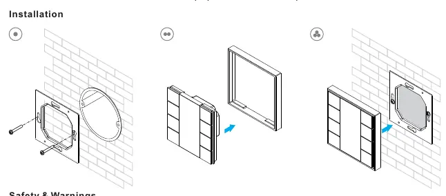
- Power Off: Do not install the device while power is applied to the circuit.
- Environment: Do not expose the device to moisture.
- Mounting: Use the provided mounting bracket to secure the controller to the wall.
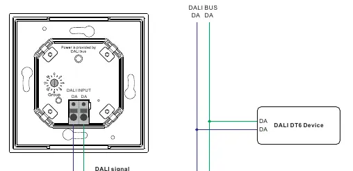
Wiring
The controller connects directly to the DALI bus. Ensure the wiring is performed according to the connection diagram. The DALI input terminals (DA, DA) should be connected to the DALI bus line. The controller can be used with multiple DALI DT6 devices on the same bus.
Operation
The controller uses a rotary switch on the back to assign the DALI group. You must assign devices on the DALI circuit to a DALI group (0-15) using a DALI master controller before using this push button controller.
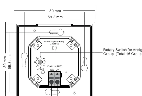
- Rotary Switch Position 0: Controls all devices on the DALI circuit through broadcast.
- Rotary Switch Position 1-15: Controls the corresponding DALI Group (X-1). For example, position 1 controls DALI Group 0, and position 15 controls DALI Group 14.
Button Functions:
- Click: Switch on/off the selected group.
- Press and hold: Turn up/down brightness.
Technical Data
- Output: DALI signal
- Power Supply: Supply by DALI Bus
- Operation Current: 30mA
- Operating Temperature: 0-40°C
- Relative Humidity: 8% to 80%
- Dimensions: 80x80x26.6mm
- Waterproof Grade: IP20
Practical help
Common problems
Device not responding to commands
Ensure that the devices on the DALI circuit have been assigned to a DALI group (0-15) using a DALI master controller first.
Controller is not controlling the intended group
Verify the rotary switch position on the back of the device. Position 0 is for broadcast; positions 1-15 correspond to DALI groups 0-14.
Before use
- Ensure power is disconnected from the circuit before installation.
- Verify that the DALI bus is active.
- Assign all DALI devices to groups using a master controller.
- Set the desired group number using the rotary switch on the back of the controller.
- Check that the environment is dry (IP20 rating).
Specs in practice
- Power Supply: DALI Bus
- The device draws power from the DALI signal line; no external power supply is needed.
- Rotary Switch (0-15)
- Used to select the DALI group to control. 0 is broadcast, 1-15 maps to groups 0-14.
Images and diagrams
- Wiring Diagram: Shows the connection of the controller to the DALI bus and the DALI DT6 devices.
- Rotary Switch: Located on the back, this dial is used to select the DALI group or broadcast mode.
Model compatibility
- Compatible with DALI DT6 devices.
- Requires a DALI master controller for initial group configuration.

Manual page author
David Miller
Documentation analyst
Organizes user manual content into clear summaries, with attention to model details, product context, and everyday usability.