Lighting / Controllers & Dimmers
Iskydance LV 0/1-10V LED Dimming Driver User Manual
Quick guide for the Iskydance LV 0/1-10V LED Dimming Driver. Learn about wiring, technical specifications, installation, and dimming compatibility.
Table of contents
Manual images
Click an image to enlargeQuick guide from the manual
The Iskydance LV is a 1-channel LED dimming driver designed for 0/1-10V signal input and PWM constant voltage output. It is compatible with active or passive 0-10V, 1-10V, 10V PWM, and RX (4-in-1) dimmers. This device is intended for indoor use (IP20) and supports logarithmic dimming for a smooth visual experience.
Technical Parameters
- Input Voltage: 5-36VDC
- Input Current: 8.5A
- Output Voltage: 5-36VDC
- Output Current: 1CH, 8A
- Output Power: 40W/96W/192W/288W (depending on 5V/12V/24V/36V input)
- PWM Frequency: 500Hz
- Dimming Range: 0-100%
- Operating Temperature: -30°C to +55°C
- Case Temperature (Max): +85°C
Mechanical Structure and Installation
The device features an installation rack for mounting. Ensure proper ventilation as the case temperature can reach up to 85°C. The unit includes terminals for:
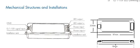
- GND
- 0/1-10V signal input
- Power input (+/-)
- LED output (+/-)
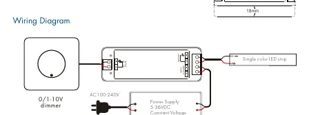
Wiring Diagram
To install the system, connect the 0/1-10V dimmer to the 0/1-10V input terminals on the driver. Connect the power supply (5-36VDC) to the power input terminals. Finally, connect the single-color LED strip to the LED output terminals. Ensure the power supply matches the voltage requirements of your LED strip.
Important Usage Notes
- Capacity: It is recommended not to connect more than 50 LED drivers to a single 0/1-10V dimmer.
- Wiring Length: The maximum length of wires from the dimmer to the LED driver should not exceed 50 meters.
- Compatibility: The input is operable via commercially available simple rotary wall switches designed for 0/1-10V dimming equipment or dedicated system central dimming controllers.
Safety and Protection
The driver includes built-in protection for reverse polarity and short circuits. It complies with EN 62479:2010, EN 62368-1:2020+A11:2020, and ETSI EN 301 489 standards.
Practical help
Common problems
Dimming signal interference or instability
Ensure the wire length between the dimmer and the LED driver does not exceed 50 meters.
Dimmer not controlling multiple drivers
Do not connect more than 50 LED drivers to a single 0/1-10V dimmer.
LED strip not lighting up
Verify that the power supply voltage (5-36VDC) matches the LED strip requirements and that polarity is correct.
Before use
- Confirm the input voltage is between 5-36VDC.
- Ensure the dimmer is compatible with 0-10V, 1-10V, 10V PWM, or RX signals.
- Check that the total load does not exceed the 8A output current limit.
- Verify the wire length from the dimmer to the driver is under 50 meters.
- Ensure the installation environment is within -30°C to +55°C.
Specs in practice
- PWM Frequency (500Hz)
- The switching frequency of the output, ensuring flicker-free dimming.
- Logarithmic Dimming
- A dimming curve designed to match human eye sensitivity for a more natural transition.
Images and diagrams
- The wiring diagram illustrates the connection sequence: Dimmer -> Driver -> Power Supply -> LED Strip.
- The mechanical structure diagram highlights the terminal layout and mounting rack positions.
Model compatibility
- Compatible with active or passive 0-10V and 1-10V dimmers.
- Supports 4-in-1 signal types: 0-10V, 1-10V, 10V PWM, and RX.

Manual page author
Michael Turner
Technical manual editor
Reviews PDF manuals for structure, safety notes, and practical product details so readers can find the right information quickly.