Lighting / Controllers & Dimmers
Zigbee+Push to DALI+0/1-10V Converter User Manual
Quick guide for the Zigbee+Push to DALI+0/1-10V Converter. Learn how to configure DIP switches, pair with Zigbee networks, use TouchLink, and wire the device for DALI or 0/1-10V control.
Table of contents
Manual images
Click an image to enlargeImportant Information
This device is a Zigbee 3.0 converter that allows control of DALI or 0/1-10V lighting systems via Zigbee signals or a push switch. Important: Never set the DIP switches while the device is powered. Always install the device with the power disconnected.
DIP Switch Configuration
The device features 10 DIP switches to configure its operation. You must select the output signal (DALI or 0/1-10V) using switch 10 first. If DALI output is selected, you must then configure the DALI device type (DT6/DT8), address mode (Address or Group), and the specific address or group number using the remaining switches.
Wiring and Installation
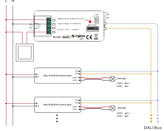
The device supports two main wiring configurations:
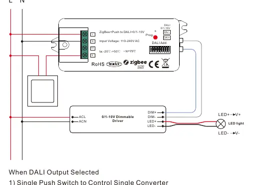
- 0/1-10V Output: Connects to a 0/1-10V dimmable driver.
- DALI Output: Connects to DALI control gears. The device has a built-in DALI bus power supply capable of supporting up to 25 DALI control gears.
Ensure all wiring is performed according to the provided diagrams in the manual. The device requires a 110-240V AC power input.
Zigbee Network Pairing
There are two primary methods to connect the device to a Zigbee network:
- Coordinator/Hub: Power on the device to enter pairing mode (light flashes twice slowly). Use your Zigbee controller interface to add the device.
- TouchLink: Allows direct pairing with a Zigbee remote without a hub. Bring the remote within 10cm of the device and initiate TouchLink commissioning.
Push Switch Control
When connected to an AC push switch, you can control the lighting manually:
- Click: Switch ON/OFF.
- Press and Hold: Increase or decrease light intensity. Release and press again to reverse the direction.
Factory Reset
If the device needs to be reset, short press the "Prog." key 5 times continuously, or reset the power 5 times from the master breaker.
Practical help
Common problems
Pairing fails
Remove the device from the previous Zigbee network first. Perform a factory reset if necessary.
TouchLink commissioning fails
Ensure the remote is within 10cm of the device. If it times out (180s), repeat the process.
DIP switch settings not taking effect
Ensure power was disconnected before changing DIP switch settings. Power must be off during configuration.
Before use
- Verify input voltage is 110-240V AC.
- Set DIP switch 10 to select between DALI or 0/1-10V output.
- If using DALI, configure DT6/DT8 and address/group modes via DIP switches.
- Ensure wiring matches the specific diagram for your output type (DALI or 0/1-10V).
- Confirm the device is not exposed to moisture (IP20 rating).
Specs in practice
- DALI Bus Power
- Built-in power supply, max 50mA, supports up to 25 DALI control gears.
- Operating Temperature
- -20°C to +50°C.
- Waterproof Grade
- IP20, suitable for indoor use only.
- Zigbee Green Power
- Supports binding up to 20 Zigbee Green Power switches.
Images and diagrams
- Wiring diagrams illustrate connections for both 0/1-10V and DALI output modes.
- DIP switch tables show the specific switch positions for selecting DALI addresses (00-63) and groups (0-15).
Model compatibility
- Compatible with universal Zigbee gateways and hubs.
- Supports Zigbee 3.0 protocol.
- Compatible with universal Zigbee remotes and TouchLink.

Manual page author
Michael Turner
Technical manual editor
Reviews PDF manuals for structure, safety notes, and practical product details so readers can find the right information quickly.