Industrial / Temperature Controllers
User Manual for Danfoss AK-RC 204B and AK-RC 205C Temperature Controller
Comprehensive user guide for the Danfoss AK-RC 204B and AK-RC 205C temperature controllers. Includes installation, wiring, initial configuration, operation modes, parameter settings, and troubleshooting.
Quick answers from the manual
Quick answer
- The AK-RC 204B/205C is a temperature controller for refrigeration. Upon first power-up, it enters a wizard mode (display shows 'InI' and flashing '0'). Select the installation type (0-13) using arrows, press SET, then set the desired temperature (SP) and press SET. p. 5
Key actions
- Install the controller p. 4
- Run initial configuration p. 5
- Access programming menu p. 14
First start
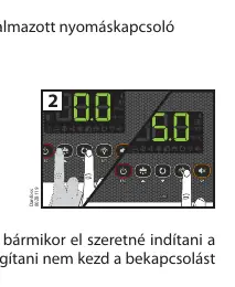
- Power on the device. When 'InI' and '0' flash, select the installation type (0-13) using arrow buttons and press SET. Then set the temperature (SP) and press SET. p. 5
Problems and fixes
E1/E2/E3 error
Sensor error (open/short circuit). Check sensor wiring.
p. 6, 12
Ad0 alarm
Door open alarm. Close the door.
p. 6, 12Error codes
| Code | Meaning | Action | Pages |
|---|---|---|---|
| E1/E2/E3 | Sensor error | Check sensor connection/wiring | p. 6, 12 |
| Ad0 | Door open alarm | Close the door | p. 6, 12 |
| AH/AL | High/Low temperature alarm | Check temperature against A1/A2 limits | p. 6, 12 |
Maintenance and reset
- Clean with soft cloth, water, and soap. Do not use abrasives. p. 3
Technical specifications
| Parameter | Value | Meaning | Pages |
|---|---|---|---|
| Power Supply | 230 V~ ± 10%, 50 Hz ± 5% | Operating voltage | p. 19 |
| Protection | IP65 | Ingress protection rating | p. 19 |
Where to find it in the PDF
- Installation p. 4
- Configuration p. 5, 14
- Technical Data p. 19
Table of contents
Manual images
Click an image to enlargeQuick guide from the manual
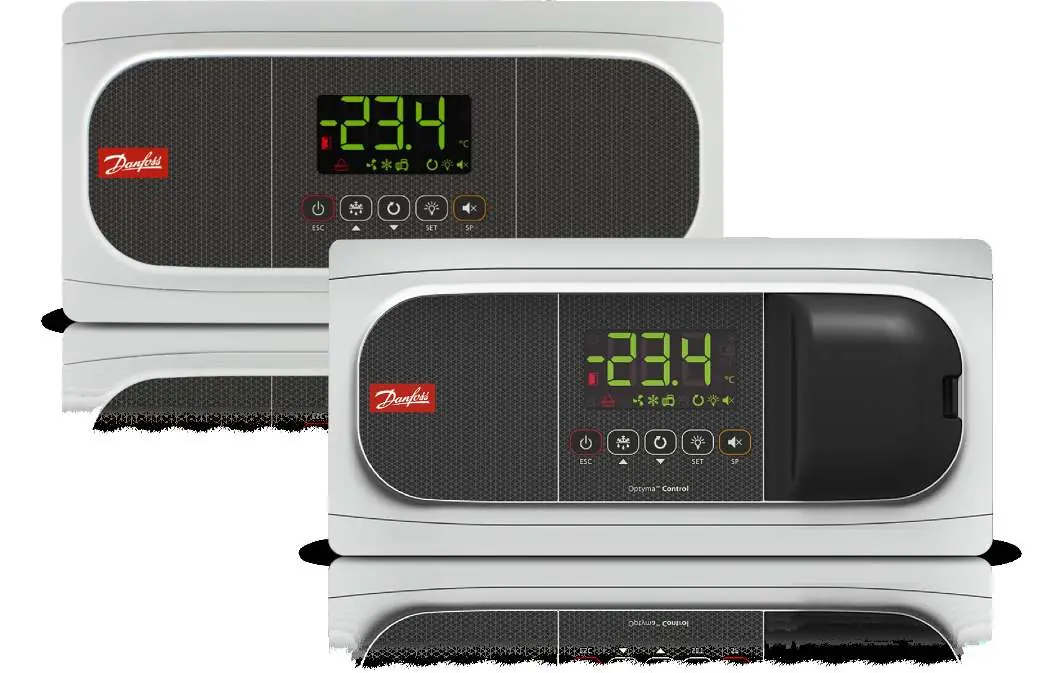
The Danfoss AK-RC 204B and 205C are temperature controllers designed for refrigeration and freezer units. Upon first power-up, the device enters a configuration wizard. The display will show 'InI' and a flashing '0'. Use the arrow buttons to select the installation type (0-13) and press SET to confirm. Then, set the desired temperature (SP) and press SET to complete the setup.
Installation
Follow these steps to install the controller:
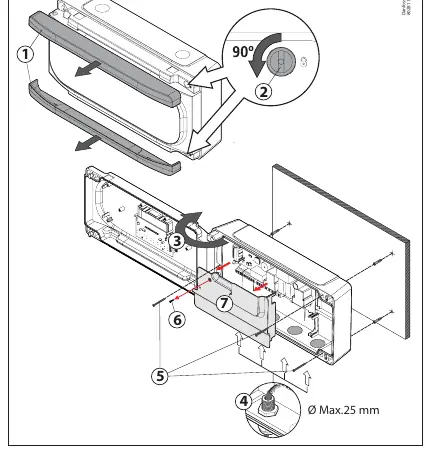
- Remove the frames (1) by pulling them out from the sides.
- Turn the screws (2) counter-clockwise 1/4 turn and open the door (3).
- Install the necessary cable glands (4) after removing the provided caps.
- Mark and drill holes in the wall using the provided template.
- Mount the device to the wall. Use the provided screws and plugs for brick walls; for metal walls (cold rooms), use the screws (5) without plugs.
- Remove the plastic cover (7) by loosening the screw (6) to access the wiring terminals.
- After wiring, replace the plastic cover (7), close the door (3), tighten the screws (2), and reattach the frames (1).
Wiring
Always disconnect the power supply before wiring. Do not install sensor cables in the same conduit as power or control cables. Use H05VV-F or NYM 1x16/3 type power cables with a minimum cross-section of 2.5 mm². Ensure relay/contactor cables are at least 2.5 mm² and resistant to 70°C.
Operation
The controller features a display and keyboard for operation:
- Standby Mode: Hold the power button for 3 seconds to activate/deactivate.
- Defrost: Hold the defrost button for 3 seconds to start/stop.
- Continuous Cycle: Hold the continuous cycle button for 3 seconds to activate/deactivate.
- Light: Press the light button to toggle the cold room light.
- Programming: Hold the SET button for 3 seconds for the simplified menu, or 6 seconds for the extended menu.
Alarms and Troubleshooting
The controller displays specific codes for errors and alarms:
- E1/E2/E3: Sensor error (open circuit, short circuit, or out of range).
- Ad0: Door open alarm (if the door remains open longer than parameter A12).
- AH/AL: High/Low temperature alarm (based on parameters A1/A2).
- AE/AES: External alarm (triggered via digital input).
- HCP: HACCP alarm (temperature exceeded h1 for longer than h2).
Maintenance
Clean the surface of the device with a soft cloth, water, and soap. Do not use abrasive cleaners, gasoline, alcohol, or solvents, as these may damage the unit.
Manufacturer information
Danfoss A/S
Practical help
Common problems
E1, E2, or E3 error code on display
Indicates a sensor error (open circuit, short circuit, or out of range). Check the sensor connection and wiring.
Ad0 alarm
The door has been open longer than the time defined in parameter A12. Close the door.
AH or AL alarm
High or Low temperature alarm. The temperature has reached the limits set in parameters A1 or A2.
Controller in Demo mode
The display alternates with temperature readings. Configuration has not been completed. Run the initial configuration wizard.
Before use
- Ensure power supply is 230V AC, 50Hz.
- Verify that NTC sensors are correctly connected.
- Check that the installation environment is protected from vibrations, water, and corrosive gases.
- Ensure cable glands are IP65 rated if required.
- Select the correct installation type (0-13) during the initial wizard.
Specs in practice
- SP (Set Point)
- The target temperature the controller aims to maintain.
- C1 (Differential)
- Hysteresis value for the 1st sensor; determines the temperature range for cooling activation.
Images and diagrams
- The installation diagram shows the sequence of opening the unit, mounting, and accessing terminals.
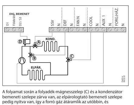
- Wiring diagrams vary based on the installation type selected in the wizard.
- Cooling control diagrams illustrate how the solenoid valve and compressor operate relative to the set point (SP) and differential (C1).
Model compatibility
- Only use Danfoss NTC sensors.
- AK-RC 204B has 4 relays; AK-RC 205C has 5 relays (includes a circuit breaker).

Manual page author
David Miller
Documentation analyst
Organizes user manual content into clear summaries, with attention to model details, product context, and everyday usability.