HVAC / Refrigeration Controllers
Danfoss AK-XM 204B Expansion Module Instructions
Quick guide for the Danfoss AK-XM 204B expansion module. Includes installation, wiring, terminal configuration, safety warnings, and technical specifications.
Quick answers from the manual
Quick answer
- The AK-XM 204B is an 8-channel digital output expansion module. It requires DIN rail mounting and strict separation between low and high voltage circuits. p. 1, 2
Key actions
- Mounting the module p. 1
- Wiring the outputs p. 2
Technical specifications
| Parameter | Value | Meaning | Pages |
|---|---|---|---|
| Max Voltage | 230 V | Maximum operating voltage | p. 1 |
| AC-1 Load | 4 A | Max ohmic load | p. 1 |
Where to find it in the PDF
- Installation and Safety p. 1
- Wiring and Configuration p. 2
Table of contents
Manual images
Click an image to enlargeQuick guide from the manual
The Danfoss AK-XM 204B is an expansion module designed for refrigeration and air conditioning control systems. This document provides essential information for safe installation, wiring, and operation. Always ensure power is disconnected before adding or removing modules to prevent electrical hazards.
Installation and mounting
The module is designed for DIN rail mounting. Ensure the installation environment meets the following conditions:
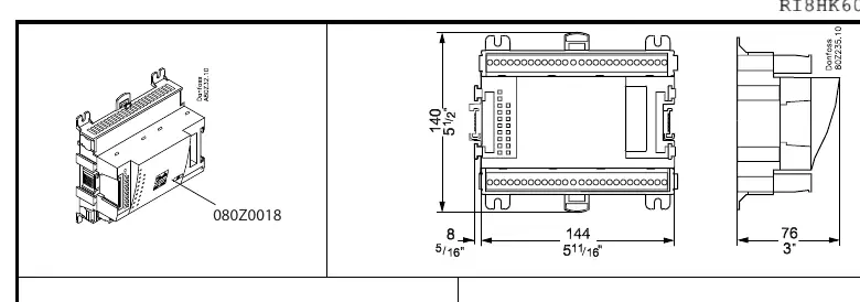
- Ambient temperature: -20°C to 55°C (-0°F to 130°F)
- Humidity: 0 - 95% RH, non-condensing
- Protection rating: IP10 / VBG4
Wiring and terminal connections
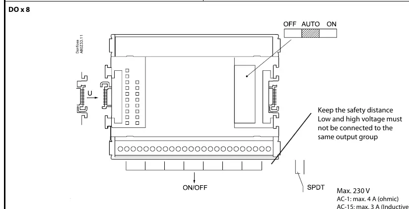
The module features 8 digital outputs (DO 1 to DO 8). It is critical to maintain safety distances between low and high voltage circuits. Do not connect low and high voltage to the same output group.
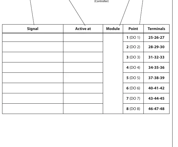
Terminal Mapping:
- DO 1: Terminals 25-26-27
- DO 2: Terminals 28-29-30
- DO 3: Terminals 31-32-33
- DO 4: Terminals 34-35-36
- DO 5: Terminals 37-38-39
- DO 6: Terminals 40-41-42
- DO 7: Terminals 43-44-45
- DO 8: Terminals 46-47-48
Configuration and operation
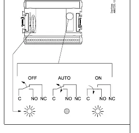
The module includes an override switch allowing for manual control (Off / Auto / On). Addressing is configured via rotary switches (x100, x10, x1) located on the unit.
Technical specifications
- Max Voltage: 230 V
- AC-1 (Ohmic): Max 4 A
- AC-15 (Inductive): Max 3 A
Manufacturer information
Danfoss A/S
Practical help
Common problems
Electrical interference or safety hazard
Ensure safety distance is maintained; do not connect low and high voltage to the same output group.
Module installation/removal issues
Always disconnect power before adding or removing modules.
Before use
- Verify power is disconnected before installation.
- Ensure ambient temperature is between -20°C and 55°C.
- Check that humidity is within 0-95% RH (non-condensing).
- Confirm DIN rail mounting space is available.
Specs in practice
- AC-15 (Inductive)
- Maximum load capacity for inductive loads is 3 A.
Images and diagrams
- The wiring diagram illustrates the terminal layout for DO 1 through DO 8.
- The override switch diagram shows the Off/Auto/On positions.
- The address diagram shows how to set the x100, x10, and x1 rotary switches.
Model compatibility
- Designed for use with compatible Danfoss controllers.
- Must be installed in an environment with IP10 / VBG4 protection standards.

Manual page author
Michael Turner
Technical manual editor
Reviews PDF manuals for structure, safety notes, and practical product details so readers can find the right information quickly.