HVAC / Refrigeration Controllers
User Manual for Danfoss EKC 202D and EKC 302D Temperature Controllers
Comprehensive user guide for Danfoss EKC 202D and EKC 302D temperature controllers. Includes installation, wiring diagrams, parameter settings, defrost configurations, and troubleshooting.
Quick answers from the manual
Quick answer
- The EKC 202D and EKC 302D are temperature controllers for refrigeration appliances. They manage refrigeration, defrosting, fans, and alarms based on sensor inputs and configurable parameters. p. 2
Key actions
- Stop regulation (r12=0), select application (o61), configure settings, then start regulation (r12=1). p. 17, 18
First start
- Follow the 'Get a good start' procedure on page 17. p. 17
Problems and fixes
High temperature alarm (A1)
Check temperature limits (A13).
p. 15
Sensor error (E25-E27)
Check sensor connections.
p. 15Error codes
| Code | Meaning | Action | Pages |
|---|---|---|---|
| A1 | High temperature alarm | Check temperature settings. | p. 15 |
| A4 | Door alarm | Check door switch. | p. 15 |
Maintenance and reset
- To return to factory settings: Cut out supply voltage, keep both buttons depressed while reconnecting supply voltage. p. 19
Technical specifications
| Parameter | Value | Meaning | Pages |
|---|---|---|---|
| Supply voltage | 230 V a.c. +10/-15 % | Power supply requirements. | p. 24 |
| Sensor types | Pt 1000, PTC, NTC | Compatible temperature sensors. | p. 24 |
Where to find it in the PDF
- Introduction p. 2
- Wiring Diagrams p. 6, 7
- Parameter Survey p. 8, 18, 19
- Technical Data p. 24
Table of contents
Manual images
Click an image to enlargeQuick guide from the manual
The Danfoss EKC 202D and EKC 302D are advanced temperature controllers designed for refrigeration appliances. To start regulation quickly, follow these steps:
- Open parameter r12 and stop the regulation (set to 0).
- Select the electric connection based on the diagrams provided in the manual (pages 6 or 7).
- Open parameter o61 and set the electric connection number.
- Open parameter r12 and start the regulation (set to 1).
- Review the factory settings and adjust parameters as needed for your specific application.
- For network setups, set the address in o03 and start the scan function in the system manager.
Introduction and Application
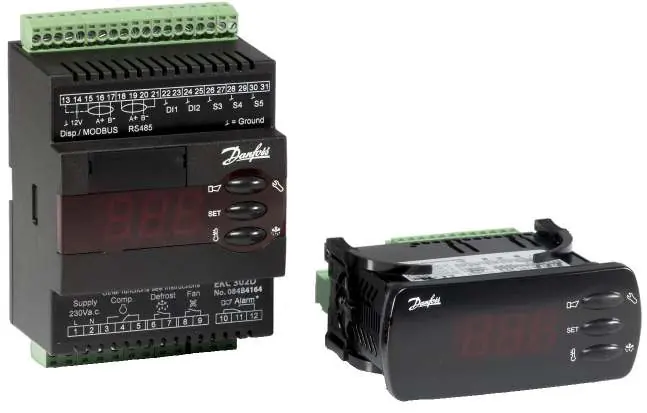
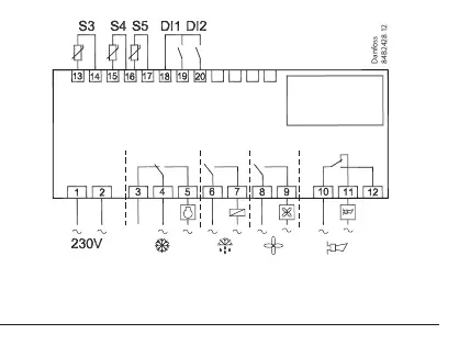
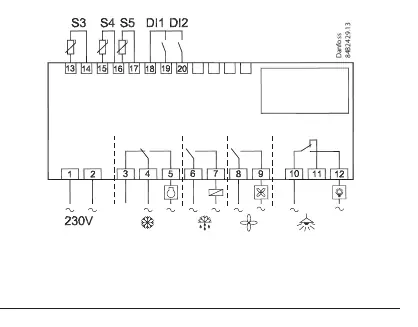
These controllers are used for temperature control in supermarket refrigeration appliances. They offer flexibility for both new installations and service. The controller manages refrigeration, fans, defrosting, rail heat, alarms, and lighting based on inputs from temperature sensors (S3, S4, S5).
Installation and Connections
The EKC 202D is designed for panel mounting (IP65 front), while the EKC 302D is a DIN rail model (IP20). Wiring diagrams for various applications are available on pages 6 and 7. Ensure that cables for sensors, digital inputs, and data communication are kept separate from other electric cables to avoid electrical noise.
Operation and Settings
The controller features a menu-driven interface. Access the menu by holding the upper button for a few seconds. Parameters are organized by function codes:
- r (Thermostat): Setpoints, differentials, and sensor selection.
- A (Alarm): Alarm delays and limits.
- c (Compressor): Running times and relay functions.
- d (Defrost): Methods (Natural, Electric, Brine), intervals, and stop temperatures.
- F (Fan): Fan control settings.
- t (Real-time clock): Defrost scheduling.
- o (Miscellaneous): Digital input configuration, network address, and access codes.
- u (Service): Status codes and sensor readings.
Troubleshooting
In case of an error, the LEDs on the front panel will flash, and the alarm relay will activate. Press the top button to view the alarm report. Common error codes include:
- A1: High temperature alarm.
- A4: Door alarm.
- E25-E27: Sensor errors (S3, S4, S5).
- E1: Controller fault.
Technical Specifications
The controllers operate on 230V AC. They support Pt 1000, PTC, or NTC sensors. Data communication is available via insert cards (EKC 202D) or fixed MODBUS (EKC 302D). Refer to the 'Data' section on page 24 for detailed relay ratings and environmental limits.
Manufacturer information
Danfoss A/S
Practical help
Common problems
High temperature alarm (A1)
Check if the temperature exceeds the set limit (A13) and verify refrigeration system operation.
Sensor error (E25, E26, E27)
Check the wiring and connection of the S3, S4, or S5 sensors. Ensure the correct sensor type is configured in o06.
Defrost not starting
Verify defrost settings (d01-d04) or attempt a manual start by holding the lower button for four seconds.
Before use
- Verify supply voltage is 230V AC.
- Ensure all connected sensors (Pt 1000, PTC, or NTC) are of the same type.
- Select the correct application mode using parameter o61.
- Configure digital inputs (DI1, DI2) according to your system requirements.
- Set the network address (o03) if using data communication.
Specs in practice
- Supply voltage
- 230V AC, 50/60 Hz.
- Sensor types
- Supports Pt 1000, PTC (1000 ohm at 25°C), or NTC (5000 ohm at 25°C).
Images and diagrams
- Wiring diagrams for different applications are provided on pages 6 and 7.
- S3/S4 are thermostat sensors; S5 is the defrost sensor.
- DI1 and DI2 are digital inputs for functions like door switches or defrost start.
Model compatibility
- EKC 202D is panel-mounted; EKC 302D is DIN rail-mounted.
- Data communication modules (LON/MODBUS) are available as accessories.
- External displays (EKA 163A/164A) can be connected.

Manual page author
Emily Carter
User documentation editor
Prepares concise manual descriptions and highlights the most useful setup, operation, and maintenance information for readers.