HVAC / Refrigeration Controllers
Installation Instructions for Danfoss AK-XM 204A Extension Module
Quick installation and wiring guide for the Danfoss AK-XM 204A extension module. Includes terminal mapping, mounting instructions, and technical specifications.
Quick answers from the manual
Quick answer
- The AK-XM 204A is an extension module with 8 digital outputs. It mounts on a DIN rail and requires careful separation of high and low voltage circuits. p. 1, 2
Key actions
- Mounting the module p. 1
- Wiring digital outputs p. 2
Technical specifications
| Parameter | Value | Meaning | Pages |
|---|---|---|---|
| Max Voltage | 230 V | Maximum operating voltage for outputs. | p. 1 |
| AC-1 | 4 A | Max ohmic load. | p. 1 |
| AC-15 | 3 A | Max inductive load. | p. 1 |
Where to find it in the PDF
- Installation and Specs p. 1
- Wiring and Addressing p. 2
Table of contents
Manual images
Click an image to enlargeQuick Guide
The Danfoss AK-XM 204A is an extension module designed for use with Danfoss refrigeration and air conditioning controllers. This guide covers the essential mounting, wiring, and configuration steps required for installation.
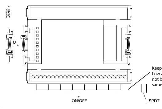
Safety Information
Warning: Ensure power is disconnected before adding or removing modules. Low and high voltage must not be connected to the same output group to maintain safety distances.
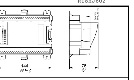
Mounting
The module is designed for DIN rail mounting. Ensure the module is securely clicked onto the rail. Refer to the mounting diagram on page 1 for the correct orientation and locking mechanism.
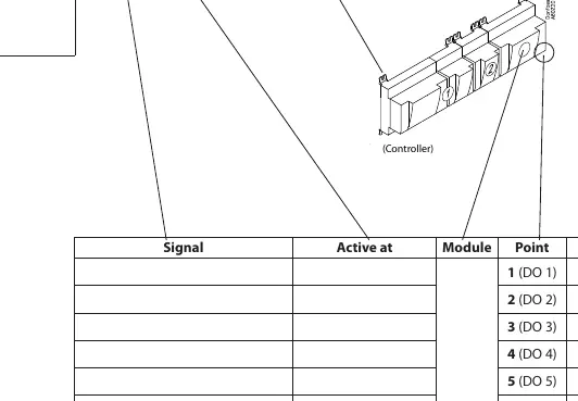
Wiring and Terminals
The AK-XM 204A features 8 digital outputs (DO). The terminals are mapped as follows:
- DO 1: Terminals 25-26-27
- DO 2: Terminals 28-29-30
- DO 3: Terminals 31-32-33
- DO 4: Terminals 34-35-36
- DO 5: Terminals 37-38-39
- DO 6: Terminals 40-41-42
- DO 7: Terminals 43-44-45
- DO 8: Terminals 46-47-48
Each output provides a Common (C), Normally Open (NO), and Normally Closed (NC) contact.
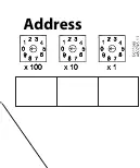
Address Setting
The module includes rotary switches to set the address. Ensure the address is configured correctly according to your specific controller setup.
Technical Specifications
- Ambient Temperature: -20°C to 55°C (-0°F to 130°F)
- Humidity: 0 - 95% RH, non-condensing
- Protection Rating: IP10 / VBG4
- Max Voltage: 230 V
- AC-1 (Ohmic): Max 4 A
- AC-15 (Inductive): Max 3 A
Disposal
This product contains electrical components and must not be disposed of with domestic waste. It must be collected separately as electrical and electronic waste in accordance with local legislation.
Manufacturer information
Danfoss A/S
Practical help
Common problems
Safety hazard due to voltage mixing
Low and high voltage must not be connected to the same output group.
Module installation/removal safety
Always ensure power is disconnected before adding or removing modules.
Before use
- Ensure power is disconnected before installation.
- Verify the ambient temperature is between -20°C and 55°C.
- Check that the installation environment is non-condensing (0-95% RH).
- Ensure high and low voltage circuits are separated.
Specs in practice
- AC-15 (Inductive)
- Maximum inductive load current is 3 A.
Images and diagrams
- The terminal mapping table on page 2 links each Digital Output (DO 1-8) to specific terminal numbers.
- The address rotary switches allow for unique identification of the module in the system.
Model compatibility
- Designed for use with Danfoss controllers.
- Requires DIN rail mounting.

Manual page author
Emily Carter
User documentation editor
Prepares concise manual descriptions and highlights the most useful setup, operation, and maintenance information for readers.