HVAC / Refrigeration Controllers
User Manual for Danfoss EKC 201C Temperature Controller
Comprehensive user guide for the Danfoss EKC 201C temperature controller. Includes installation instructions, wiring diagrams, parameter settings, defrost configuration, and troubleshooting steps.
Quick answers from the manual
Quick answer
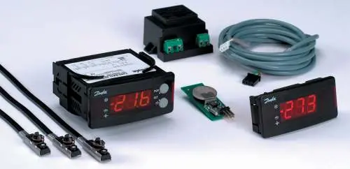
- The Danfoss EKC 201C is a temperature controller for refrigeration appliances, featuring double thermostat functionality, coordinated defrost, and data communication capabilities. p. 2
Key actions
- Access menu p. 10
- Change parameter p. 10
- Manual defrost p. 6
First start
- Connect sensors, verify sensor type in o06, and configure thermostat settings (r07, r08) based on application requirements. p. 8, 13, 15
Problems and fixes
E1
Fault in controller.
p. 9
E4/E5
Defrost sensor error (disconnected/short-circuited).
p. 9
E7/E8
Sout sensor error.
p. 9
E9/E10
Sin sensor error.
p. 9Maintenance and reset
- Return to factory settings: Cut out supply voltage, keep both buttons depressed while reconnecting supply voltage. p. 11
Technical specifications
| Parameter | Value | Meaning | Pages |
|---|---|---|---|
| Supply voltage | 12 V a.c./d.c. | Operating voltage range. | p. 12 |
| Measuring range | -60 to +50°C | Temperature sensing range. | p. 12 |
| IP Rating | IP 54 | Ingress protection rating. | p. 12 |
Where to find it in the PDF
- Introduction p. 2
- Functions p. 3
- Survey of functions p. 4, 5, 6, 7
- Fault messages p. 9
- Operation p. 10
- Menu survey p. 11
- Technical data p. 12
- Connections p. 13
Table of contents
Manual images
Click an image to enlargeQuick Guide
The Danfoss EKC 201C is a temperature controller designed for refrigeration appliances. It features a double thermostat function, allowing for precise temperature control based on air currents before and after the evaporator. The controller supports coordinated defrost, night lid detection, and data communication capabilities.
Installation and Connections
The controller is designed for quick installation using plug connections, eliminating the need for screw terminals. Ensure the supply voltage is 12 V a.c./d.c. (+15/-15%).
Wiring Requirements:
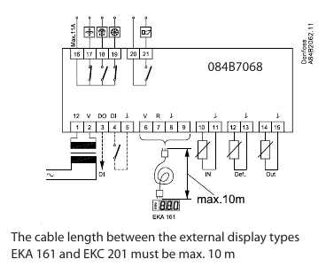
- Sensors: The Sout sensor must be connected. The Sdef sensor is optional. The Sin sensor must be connected if the active thermostat setting (o14) is set to 'Aut' and the display sensor setting (o17) is not set to 'Out'.
- Plugs: Use the appropriate Phoenix-type green plugs or AMP module 2 black plugs as specified in the connection section.
- Data Communication: If a data communication module is installed, ensure the cable is installed correctly according to separate literature (RC.8A.C).
Operation and Display
The front panel features a 3-digit display and two buttons for operation. Three LEDs indicate the system's status: refrigeration, defrost, and fan operation. If an alarm occurs, all three LEDs will flash.
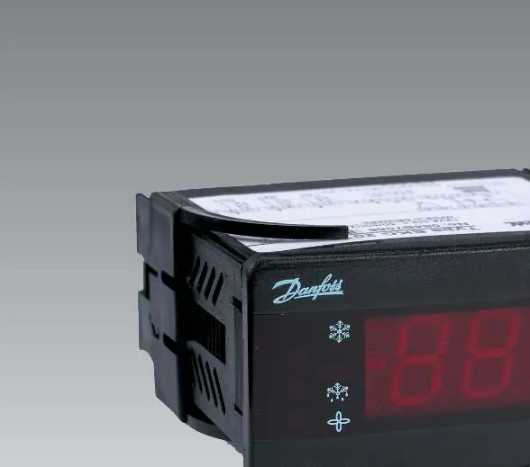
Button Functions:
- Upper Button: Access the menu (or cut out an alarm).
- Lower Button: Access changes.
- Both Buttons Simultaneously: Save a change.
Configuration and Parameters
To change settings, push the upper button for a few seconds to enter the parameter code menu. Navigate to the desired code, push both buttons simultaneously to view the value, adjust using the buttons, and save by pushing both buttons again.
Key Parameters:
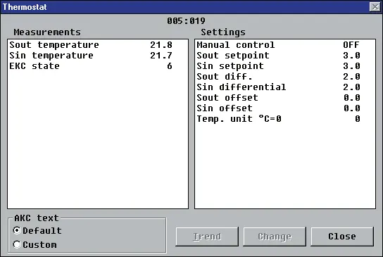
- r05: Temperature unit (°C or °F).
- r07/r08: Differential settings for Sout and Sin.
- A03/A04: Alarm delays for temperature and door.
- c01/c02: Compressor running times (Min. ON/OFF time).
- d01-d13: Defrost settings, including interval, duration, and sensor selection.
- o02: Digital input configuration.
Defrost Management
The controller supports periodic defrosting. You can set the interval (d03) or use a real-time clock module for specific times of the day. Coordinated defrost can be achieved via wire connections between controllers or via data communication. During defrost, the display will show '-d-' if configured.
Troubleshooting and Alarms
In an error situation, the LEDs will flash, and the alarm relay will be activated. Push the top button to view the alarm report on the display.
Common Error Codes:
- E1: Fault in controller.
- E4/E5: Defrost sensor error (disconnected/short-circuited).
- E7/E8: Sout sensor error.
- E9/E10: Sin sensor error.
- A4: Door alarm.
Technical Specifications
The controller operates on 12 V a.c./d.c. with a power consumption of 2.5 VA. It supports Pt 1000 or PTC (R25 = 1000 ohm) sensors. The measuring range is -60 to +50°C with an IP 54 density rating. Relays are rated for specific ohmic and inductive loads as detailed in the data section.
Manufacturer information
Danfoss A/S
Practical help
Common problems
Alarm LED flashing
Push the top button to view the alarm report on the display and identify the error code.
Controller not starting
Verify that the sensors used match the type set in parameter o06 (Pt 1000 or PTC). Check the Sin thermostat setting and the controller's operating status.
Defrost not starting
Check the interval setting (d03) or ensure the real-time clock module is correctly configured if used.
Before use
- Ensure supply voltage is 12 V a.c./d.c.
- Connect the Sout sensor (required).
- Verify sensor type (Pt 1000 or PTC) matches parameter o06.
- Ensure proper wiring of relay outputs (refrigeration, fan, defrost, alarm).
- If using data communication, ensure the module is correctly installed.
Specs in practice
- Supply voltage
- 12 V a.c./d.c. +15/-15 %.
- Measuring range
- -60 to +50°C.
Images and diagrams
- Wiring diagram shows connections for supply voltage, digital inputs, sensors, and relay outputs.
- Posterior view identifies terminal blocks for relays, alarms, and data communication.
Model compatibility
- Compatible with Danfoss gateway AKA 243 for data communication.
- Supports Pt 1000 or PTC sensors.

Manual page author
Emily Carter
User documentation editor
Prepares concise manual descriptions and highlights the most useful setup, operation, and maintenance information for readers.