Industrial / Temperature Controllers
Installation Guide for Danfoss AK-RC 204B and 205C Temperature Controller
A comprehensive installation and configuration guide for the Danfoss AK-RC 204B and 205C temperature controllers. Includes wiring instructions, initial setup wizard, parameter settings, and troubleshooting.
Quick answers from the manual
Quick answer
- The Danfoss AK-RC 204B/205C is a temperature controller for cold rooms. Installation requires selecting an 'InI' configuration type on first startup and wiring according to local regulations. Always disconnect power before wiring. p. 1, 3
Key actions
- Enter configuration wizard p. 3
- Access short menu p. 4
- Access extended menu p. 4
First start
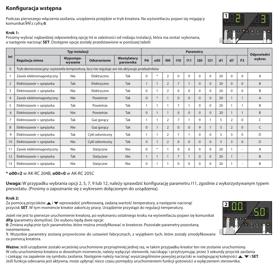
- On first power-up, the device enters the wizard. Select the 'InI' option from the table and press SET. p. 3
Problems and fixes
E1/E2/E3
Sensor fault (open circuit, short circuit, or out of range).
p. 7
Ad0
Door open alarm.
p. 7Maintenance and reset
- To reset parameters to factory defaults, use option 1 in the dFp menu after the wizard. p. 3
Technical specifications
| Parameter | Value | Meaning | Pages |
|---|---|---|---|
| Power Supply | 230V AC ±10% | Operating voltage | p. 8 |
| Protection | IP65 | Ingress protection rating | p. 8 |
Where to find it in the PDF
- Warnings and Wiring p. 1
- Keyboard and Status p. 2
- Initial Configuration p. 3
- Parameters p. 4, 5, 6
- Technical Data p. 8
Table of contents
Manual images
Click an image to enlargeQuick Guide
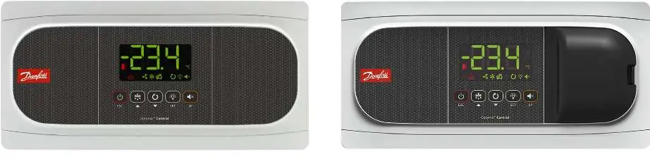
The Danfoss AK-RC 204B and 205C are temperature controllers designed for cold rooms and freezers. Always disconnect the power supply before performing any wiring. Ensure that sensor cables are not routed in the same cable ducts as power or control cables. The device requires IP65-compliant cable glands to maintain its protection rating.
Keyboard and Operation
The front panel features several buttons for operation:
- Standby: Press and hold for 3 seconds to enter/exit standby mode.
- Defrost: Press for 3 seconds to toggle defrost.
- Continuous Cycle: Press and hold for 3 seconds to toggle.
- Light: Single press to toggle chamber lighting.
- SET: Used for menu navigation and confirming values. Hold for 3 seconds for the short menu or 6 seconds for the extended menu.
- Alarm/SP: View setpoint or mute alarms.
Initial Configuration
Upon the first power-up, the device enters a configuration wizard. The display will show a flashing 0. Select the appropriate InI option from the configuration table based on your installation type (e.g., solenoid valve, compressor, defrost type) and press SET. If the wizard does not start automatically, you can trigger it by turning off the controller (hold power button for 3 seconds) and then pressing the Up, Down, and SET buttons in sequence.
Configuration Menus
The controller features two configuration levels:
- Short Menu: Access by holding SET for 3 seconds. Allows quick configuration of common parameters (SP, C1, d0, d1, d4, F3, A1, A2).
- Extended Menu: Access by holding SET for 6 seconds. Allows full configuration of all device parameters.
Note: If a password is configured (b10=1 or 2), you must enter the password (PAS) to access these menus.
Parameters Overview
Parameters are grouped into categories:
- rE: Regulation and control (setpoints, hysteresis, compressor delays).
- dEF: Defrost settings (frequency, duration, type).
- FAn: Evaporator fan settings.
- AL: Alarm settings (temperature limits, delays).
- bcn: Basic configuration (passwords, communication).
- In0: Inputs and outputs configuration.
- HCP: HACCP alarm settings.
Troubleshooting
The device displays specific messages for errors:
- E1/E2/E3: Sensor fault (open circuit, short circuit, or out of range).
- Ad0: Door open alarm.
- AH/AL: High/Low temperature alarm.
- hCP: HACCP alarm.
Technical Specifications
The controller operates on 230V AC ±10%, 50Hz. It features an IP65 protection rating and uses NTC sensors. The device is designed for continuous operation with a relay capacity suitable for refrigeration equipment.
Manufacturer information
Danfoss A/S
Practical help
Common problems
Sensor error (E1, E2, E3)
Check the sensor wiring for open circuits, short circuits, or if the temperature is outside the sensor range.
Alarm HACCP
The temperature exceeded the limit defined in h1 for longer than h2. Check the cooling system and reset the alarm.
Controller not responding to buttons
Check if the keyboard is locked (b10 parameter). If locked, enter the password (PAS) to unlock.
Before use
- Disconnect power before starting any wiring.
- Ensure cable glands used for installation provide at least IP65 protection.
- Do not route sensor cables in the same conduit as power cables.
- Select the correct installation type (InI) during the first startup wizard.
- Verify local regulations before installation.
Images and diagrams
- The manual includes a configuration table (InI) that maps installation types to specific parameter settings (Pd, o00, I00, etc.).
Model compatibility
- Requires NTC sensors supplied by Danfoss.
- AK-RC 204B and 205C have specific differences in relay availability and sensor inputs.

Manual page author
Emily Carter
User documentation editor
Prepares concise manual descriptions and highlights the most useful setup, operation, and maintenance information for readers.