HVAC / Refrigeration Controllers
User Manual for Danfoss Optyma AK-RC 204B, 205C, 305W-SD Refrigeration Controller
Comprehensive user guide for the Danfoss Optyma AK-RC 204B, 205C, and 305W-SD refrigeration controllers. Includes installation instructions, wiring diagrams, configuration settings, and technical specifications.
Table of contents
Manual images
Click an image to enlargeQuick Guide from the Manual
The Danfoss Optyma AK-RC series (204B, 205C, 305W-SD) are refrigeration controllers designed for cold rooms and freezers. The primary configuration step involves selecting the correct application (InI) during the initial setup, which determines the controller's logic and relay behavior. Ensure the power supply matches the specific model requirements before installation.
Functions and Features
The controller manages various components of a cold room system, including:
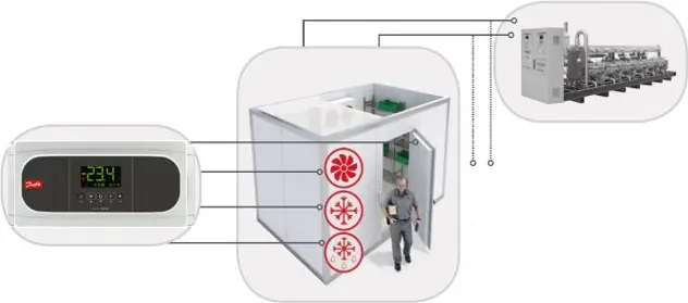
- Compressor
- Crankcase heater
- Evaporator fans
- Defrost heater (up to 2 evaporators)
- Solenoid valve
- Cold room lighting
- Door frame and drainage heating elements
- Door activity and alarms (temperature, open door)
Installation and Mounting
The controller is designed for fixed indoor mounting. Follow these steps for installation:


- Ensure the mounting surface is suitable for the dimensions (290 x 141 x 84.4 mm).
- Use the provided drilling template to mark and drill holes (3 mm or 5 mm depending on the wall type).
- Secure the unit firmly.
- Ensure proper clearance for wiring and maintenance.
Wiring and Configuration
Wiring must be performed according to the specific diagram corresponding to the selected application (InI code). Refer to the wiring diagrams in the manual for your specific model (AK-RC 204B, 205C, or 305W-SD).
- InI Selection: Run the startup assistant to select the application that matches your installation (e.g., Solenoid, Compressor, Defrost type).
- Sensors: The kit includes 2 NTC 10K sensors.
- Modbus: Standard Modbus connectivity is available for third-party integration.
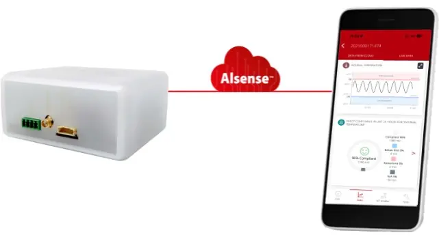
Cloud Connectivity
The system supports remote monitoring via the Danfoss IoT Cloud service. Use the PR-SC4 module to enable cloud connectivity and access data via the ProsaLink smartphone application. This allows for remote maintenance, alarm notifications via email, and HACCP reporting.
Technical Data
Key technical specifications include:
- Power Supply: 230V AC (204B/205C) or 100-240V AC (305W).
- Protection: IP65 rated.
- Operating Temperature: -10 to 50°C (varies by model).
- Relay Outputs: Various SPDT/SPST configurations rated up to 20A.
Manufacturer information
Danfoss A/S
Practical help
Common problems
Controller not regulating temperature
Verify if the unit is in Demo mode (InI=0). In this mode, the display shows temperature but relays are not activated.
Communication error with ProsaLink/Cloud
Ensure Modbus address (parameter b20) is set to 1 and communication speed (parameter b21) is set to 1 (19200 baud).
Before use
- Verify that the power supply voltage matches the controller model (230V or 100-240V).
- Ensure NTC sensors are correctly connected to the S1/S2 terminals.
- Identify the correct application (InI) based on your refrigeration system setup.
- Check the wiring diagram specific to your InI code before powering on.
- Ensure the mounting location is dry and within the operating temperature range (-10 to 50°C).
Images and diagrams
- Wiring diagrams are categorized by InI codes (1-13). Always match the diagram to your specific InI configuration.
- Ensure all power is disconnected before performing any wiring operations.
- The diagrams indicate connections for RS485, NTC sensors, Digital Inputs, and various relay outputs.
Model compatibility
- AK-RC 305W-SD supports a wider voltage range (100-240V AC).
- Some applications (InI 9-13) are not available on the 305W-SD model.
- ProsaLink connectivity requires the PR-SC4 module.

Manual page author
David Miller
Documentation analyst
Organizes user manual content into clear summaries, with attention to model details, product context, and everyday usability.