Industrial / Temperature Controllers
User Guide for Danfoss EKC 202A, 202B, 202C Temperature Controller
Comprehensive user guide for Danfoss EKC 202A, 202B, and 202C temperature controllers. Includes setup, operation, menu parameters, wiring diagrams, and troubleshooting.
Quick answers from the manual
Quick answer
- The Danfoss EKC 202 series are temperature controllers for refrigeration. They manage cooling, defrosting, fans, and alarms. Settings are adjusted via the front panel buttons and menu parameters. p. 2, 5
Key actions
- Access menu p. 5
- Manual defrost p. 5
First start
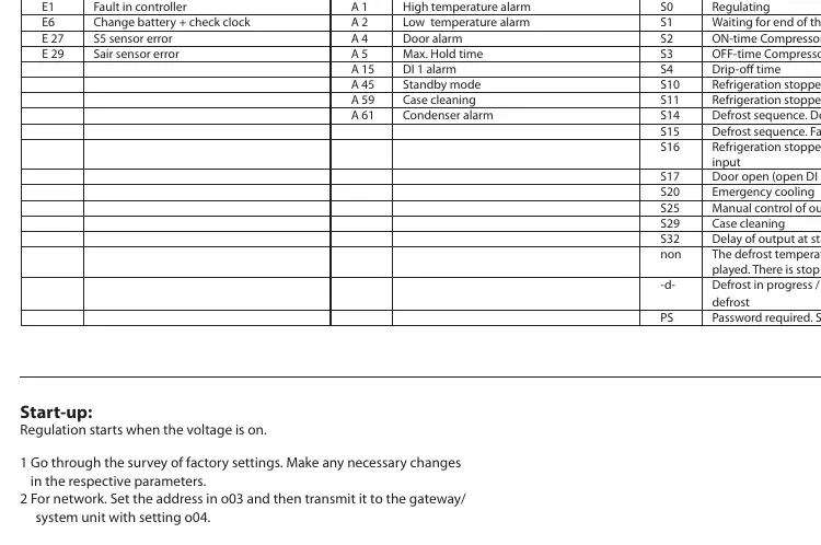
- Go through factory settings and make necessary changes. p. 7
Problems and fixes
E1
Fault in controller
p. 14
E6
Fault in real-time clock
p. 14Error codes
| Code | Meaning | Action | Pages |
|---|---|---|---|
| E1 | Fault in controller | Contact service | p. 14 |
| E27 | S5 sensor error | Check sensor | p. 14 |
Maintenance and reset
- Return to factory settings p. 7
Technical specifications
| Parameter | Value | Meaning | Pages |
|---|---|---|---|
| Supply voltage | 230V AC | Power input | p. 18 |
| Enclosure | IP65 | Front panel protection | p. 18 |
Where to find it in the PDF
- Introduction p. 2
- Connections p. 16
- Technical Data p. 18
Table of contents
Manual images
Click an image to enlargeQuick guide from the manual
The Danfoss EKC 202 series (A, B, and C) are temperature controllers designed for refrigeration appliances. They manage temperature regulation, defrosting, fans, alarms, and lighting. The controller features an IP65 front panel with integrated buttons and a 3-digit display.
Operation
The front panel includes three buttons and a display. LEDs indicate the status of refrigeration, defrost, and fan functions. If an alarm occurs, the LEDs will flash.
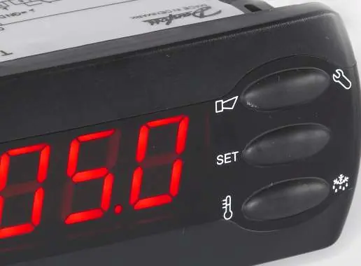
- Set menu: Push the upper button for a few seconds to enter the parameter menu. Use the upper/lower buttons to navigate, the middle button to select, and the middle button again to save.
- Set temperature: Push the middle button until the temperature value appears, then use the upper/lower buttons to adjust.
- Manual defrost: Push the lower button for four seconds.
Defrosting
Defrosting can be initiated in several ways: at fixed time intervals, based on refrigeration time, via digital input, manually, or via data communication. The controller supports natural, electric, or gas defrosting. The defrost stop can be based on time or temperature (using a defrost sensor).
Connections
The controller requires a 230V AC power supply. Sensors (Sair for thermostat, S5 for defrost) and digital inputs must be wired according to the specific model (A, B, or C). Keep sensor and digital input cables separate from power cables (minimum 10 cm distance) to avoid electrical noise.
Troubleshooting
In case of an error, the LEDs will flash and the alarm relay will activate. Press the top button to view the alarm report. Common fault codes include E1 (Controller fault), E6 (Real-time clock fault), E27 (S5 sensor error), and E29 (Sair sensor error).
Technical Data
The controller operates between 0 and +55°C. It supports Pt 1000, PTC 1000, or NTC-M2020 sensors. The enclosure is IP65 rated from the front. Relay outputs vary by model: EKC 202A (2 relays), EKC 202B (3 relays), and EKC 202C (4 relays).
Manufacturer information
Danfoss A/S
Practical help
Common problems
E1: Fault in controller
Internal controller error; contact service.
E6: Fault in real-time clock
Check battery or reset the clock.
E27: S5 sensor error
Check the S5 sensor connection and wiring.
E29: Sair sensor error
Check the Sair sensor connection and wiring.
Before use
- Verify supply voltage is 230V AC.
- Ensure all sensors are of the same type (Pt 1000, PTC 1000, or NTC).
- Check wiring diagrams for your specific model (A, B, or C).
- Ensure sensor and DI cables are separated from power cables by at least 10 cm.
- Configure parameters according to your specific refrigeration application.
Specs in practice
- Supply voltage
- 230V AC (+10/-15%), 50/60 Hz.
- Operating temperature
- 0 to +55°C.
Images and diagrams
- Wiring diagrams illustrate connections for Sair, S5, Digital Input (DI), and relay outputs.
- Relay outputs are model-specific: A (2 relays), B (3 relays), C (4 relays).
Model compatibility
- EKC 202A: 2 relay outputs.
- EKC 202B: 3 relay outputs (includes fan control).
- EKC 202C: 4 relay outputs (includes fan and alarm/light control).

Manual page author
Michael Turner
Technical manual editor
Reviews PDF manuals for structure, safety notes, and practical product details so readers can find the right information quickly.