Hvac / Thermostats Controls
Installation Guide for Danfoss Aveo 015G4050 Thermostatic Sensors
Quick installation and configuration guide for Danfoss Aveo RA/VL and RA/V thermostatic sensors, including temperature limitation settings and mounting procedures.
Table of contents
Manual images
Jump to the sectionQuick guide from the manual
This document provides essential instructions for the installation and configuration of Danfoss Aveo RA/VL and RA/V thermostatic sensors. It covers the physical mounting process, setting temperature limits (both maximum and minimum), and using the blind mark feature.
Installation
The installation process is straightforward and requires no special tools for the sensor attachment itself. Ensure the sensor is correctly aligned with the valve body before securing it.
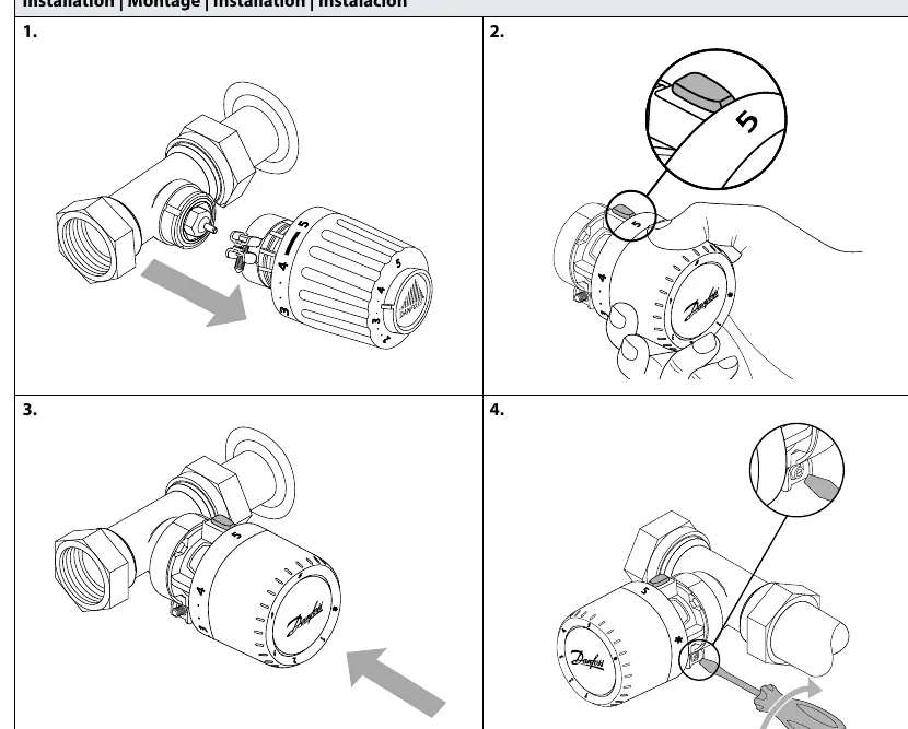

- Align the sensor with the valve body.
- Ensure the sensor is set to the maximum position (5) for easier installation.
- Push the sensor firmly onto the valve.
- Secure the sensor by tightening the connection, using a tool if necessary to ensure a firm fit.
Temperature Limitation
You can restrict the temperature range of the sensor to prevent overheating or overcooling. This is done by inserting a limiter pin into the internal mechanism.
Maximum Temperature Limitation
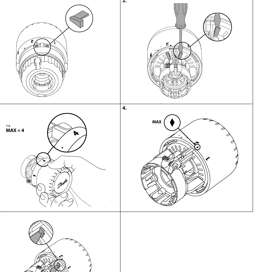
- Remove the limiter pin from the storage position.
- Use a screwdriver to access the internal setting mechanism.
- Set the desired maximum temperature (e.g., position 4).
- Insert the limiter pin into the corresponding slot to lock the maximum setting.
Minimum Temperature Limitation
- Access the internal mechanism as described above.
- Set the desired minimum temperature (e.g., position 2).
- Insert the limiter pin into the slot corresponding to the minimum temperature limit.
Blind mark
The sensor features a blind mark indicator, which allows for tactile identification of the setting, useful for visually impaired users or for setting the temperature without looking at the dial.
Manufacturer information
Danfoss A/S
Practical help
Common problems
Sensor does not fit on the valve
Ensure you are using the correct model (RA/VL or RA/V) for your specific valve type.
Temperature range is too wide
Use the temperature limitation procedure to insert a limiter pin at your desired min or max setting.
Before use
- Identify your valve type (RA/VL or RA/V).
- Ensure the sensor dial is set to position 5 before mounting.
- Have a small screwdriver ready for temperature limitation adjustments.
- Verify you have the correct limiter pin (Code no. 013G1246).
Images and diagrams
- Page 1 shows the step-by-step mounting process onto the valve.
- Page 2 illustrates the procedure for setting a maximum temperature limit.
- Page 3 illustrates the procedure for setting a minimum temperature limit.
- Page 4 explains the blind mark feature for tactile setting.
Model compatibility
- The series includes specific models for RA/VL and RA/V valve types.
- Ensure the correct adapter is used for the specific valve body.

Manual page author
Emily Carter
User documentation editor
Prepares concise manual descriptions and highlights the most useful setup, operation, and maintenance information for readers.