Hvac / Thermostats Controls
Installation Guide for Danfoss Redia RA click Thermostatic Sensors
Quick installation and configuration guide for Danfoss Redia RA click thermostatic sensors, covering mounting, remote sensor setup, temperature limitation, and theft protection.
Table of contents
Manual images
Jump to the sectionQuick guide from the manual
This document provides essential instructions for the installation and configuration of the Danfoss Redia RA click thermostatic sensor series. It covers standard mounting, BIV installation, remote sensor placement, temperature range limiting, and theft protection procedures.
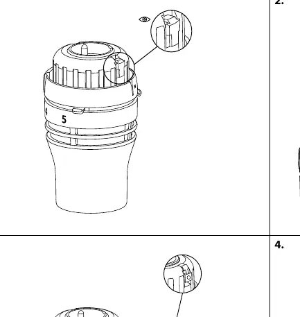
Installation
The RA click system is designed for quick mounting:
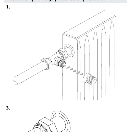
- Ensure the valve body is prepared.
- Align the sensor with the valve body.
- Press the sensor firmly onto the valve until you hear a distinct click, indicating it is locked in place.
BIV Installation
For BIV (Built-in Valve) configurations:
- Remove the protective cap from the valve.
- Align the sensor with the valve interface.
- Push the sensor onto the valve until it clicks securely.
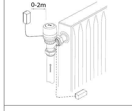
Remote sensor
The remote sensor can be positioned at a distance of 0-2 meters from the radiator valve. Ensure the sensor is mounted in a location that accurately reflects the room temperature, away from direct heat sources or drafts. Use the provided mounting bracket to secure the remote sensor unit to the wall.
Temperature Limitation
You can restrict the temperature range to prevent overheating or freezing:
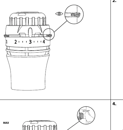
Maximum Temperature Limitation
- Identify the current setting.
- Rotate the sensor to the desired maximum limit.
- Use the internal limiter mechanism to lock the maximum position (e.g., set to 4).
Minimum Temperature Limitation
- Rotate the sensor to the desired minimum limit.
- Adjust the internal limiter to prevent the dial from turning below the selected minimum value (e.g., set to 2).
Theft protection
To prevent unauthorized removal of the sensor:
- Insert the theft protection clip into the designated slot on the sensor body.
- Secure it using a screwdriver.
- To remove the protection, use a screwdriver to release the clip mechanism before detaching the sensor from the valve.
Manufacturer information
Danfoss A/S
Practical help
Common problems
Sensor does not click onto the valve
Ensure the valve body is clean and the sensor is properly aligned before applying firm pressure.
Need to remove a theft-protected sensor
Use a screwdriver to carefully release the locking clip before attempting to pull the sensor off the valve.
Before use
- Verify the valve type is compatible with RA click.
- Ensure the area for the remote sensor is free from obstructions.
- Check that the sensor is not covered by curtains or furniture.
- Have a small screwdriver ready for theft protection or limitation adjustments.
Images and diagrams
- The 'click' icon indicates the point where the sensor is fully engaged with the valve.
- The 'MAX' and 'MIN' indicators show where to set the internal limiters on the dial.
- The screwdriver icons illustrate the specific points for engaging or disengaging the theft protection clip.
Model compatibility
- Designed for use with Danfoss RA click valve bodies.
- Remote sensor must be placed within 2 meters of the valve.

Manual page author
David Miller
Documentation analyst
Organizes user manual content into clear summaries, with attention to model details, product context, and everyday usability.