Hvac / Thermostats Controls
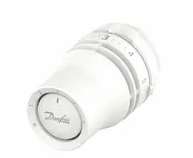
Installation Guide for Danfoss Redia RA click Thermostatic Sensors
Quick installation and configuration guide for Danfoss Redia RA click thermostatic sensors, covering mounting, temperature limitation, and theft protection.
Table of contents
Manual images
Jump to the sectionQuick guide from the manual
This document provides essential instructions for the installation, temperature limitation, and security setup of the Danfoss Redia RA click thermostatic sensors. It is intended for users performing initial setup or adjusting operational parameters.
Installation
The RA click system is designed for quick mounting on compatible radiator valves:
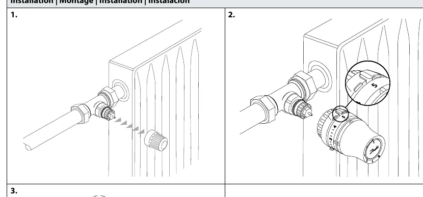
- Ensure the valve is prepared.
- Align the sensor with the valve body.
- Press the sensor firmly onto the valve until you hear a distinct click, indicating it is securely locked in place.
BIV Installation
For BIV (Built-in Valve) configurations, follow the same click-on procedure by aligning the sensor with the valve interface and pressing until it clicks.
Uninstall
To remove the sensor, firmly grip the unit and pull it away from the valve body while ensuring the locking mechanism is released.
Temperature Limitation
You can restrict the temperature range to prevent overheating or excessive cooling:
Maximum Temperature Limitation
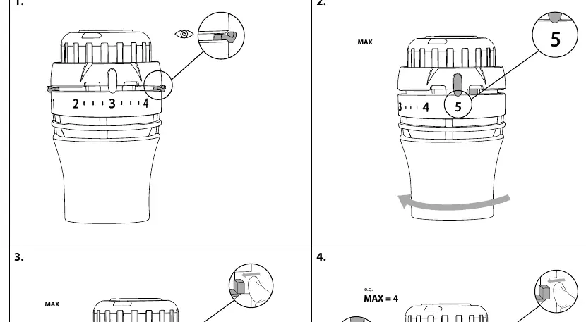
- Identify the current setting.
- Rotate the sensor to the desired maximum value (e.g., 5).
- Use the internal limiter mechanism to lock the maximum position.
- Adjust the limiter to the specific value (e.g., 4) to restrict the dial movement.
Minimum Temperature Limitation
- Rotate the sensor to the desired minimum value (e.g., 2).
- Engage the limiter to prevent the dial from being turned below the set point.
Shut off
The sensor can be set to a shut-off position to stop flow through the radiator. Follow the visual indicators on the device to rotate the dial to the closed position.
Theft protection
To prevent unauthorized removal of the sensor:
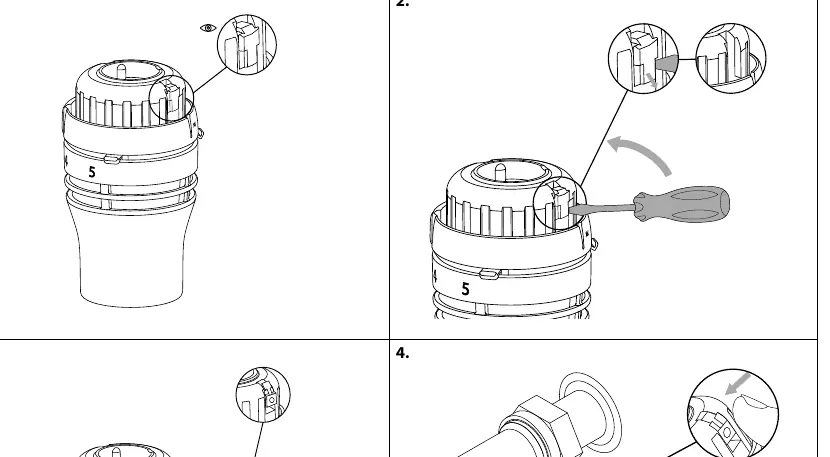
- Install the theft protection clip onto the sensor housing.
- Use a screwdriver to secure the locking screw.
- To remove, use the screwdriver to loosen the locking screw and detach the protection clip.
Manufacturer information
Danfoss A/S
Practical help
Common problems
Sensor does not click into place
Ensure the valve body is clean and compatible, and that you are applying firm, even pressure directly onto the valve.
Unable to remove the sensor
Check if the theft protection clip is installed. If so, you must first remove the locking screw using a screwdriver.
Before use
- Verify compatibility with your radiator valve type.
- Ensure the valve is free of debris.
- Have a small screwdriver ready if you intend to install theft protection.
Specs in practice
- Temperature Limitation
- Mechanical stops that restrict the rotation of the dial to set min/max temperature bounds.
Images and diagrams
- The 'click' icon indicates the point where the sensor is fully engaged with the valve.
- The 'eye' icon in the temperature limitation section highlights the internal limiter tab that must be adjusted.
- The 'screwdriver' icon indicates where to apply force for theft protection installation or removal.
Model compatibility
- Designed specifically for the Danfoss RA click valve interface.

Manual page author
Emily Carter
User documentation editor
Prepares concise manual descriptions and highlights the most useful setup, operation, and maintenance information for readers.