Hvac / Thermostats Controls
Installation Guide for Danfoss Aveo Tamperproof Remote Sensor
Quick installation and configuration guide for the Danfoss Aveo Tamperproof remote thermostatic sensor, covering mounting, temperature limitation, and theft protection.
Table of contents
Manual images
Jump to the sectionQuick guide from the manual
This document provides essential instructions for the installation and configuration of the Danfoss Aveo Tamperproof remote thermostatic sensor. It covers physical mounting, setting maximum and minimum temperature limits, and installing theft protection features.
Installation
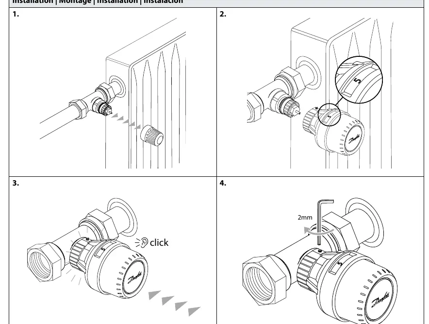
- Ensure the valve body is prepared.
- Align the sensor with the valve.
- Press the sensor onto the valve until you hear a click.
- Secure the sensor using a 2mm hex key.
Remote sensor setup
The remote sensor can be positioned at a distance of 0-2 meters from the radiator valve. Ensure the sensor unit is mounted securely to the wall using the provided bracket, which clicks into place.
Temperature Limitation
The sensor allows for both maximum and minimum temperature settings to prevent unauthorized adjustments.
Setting Maximum Temperature
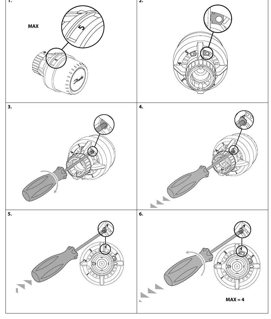
- Set the sensor to the desired maximum position (e.g., 5).
- Locate the limitation pin inside the sensor.
- Use a screwdriver to adjust the pin position to the desired limit.
- Secure the setting to lock the maximum temperature.
Setting Minimum Temperature
- Set the sensor to the desired minimum position.
- Adjust the internal limitation pin using a screwdriver to restrict the dial movement.
- Verify the new minimum setting is locked.
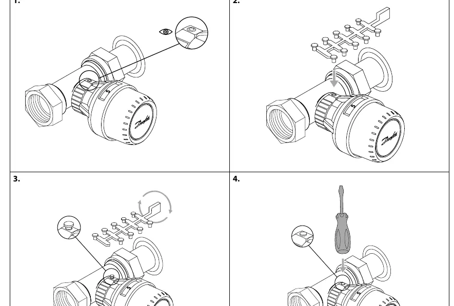
Theft protection
To prevent theft, a locking mechanism can be installed on the sensor connection. Insert the theft protection pins into the designated slots on the sensor collar and secure them to prevent the sensor from being unscrewed from the valve.
Scale cover
A scale cover can be snapped onto the sensor dial to protect the temperature markings and provide a clean, tamper-resistant finish.
Manufacturer information
Danfoss A/S
Practical help
Common problems
Sensor is loose on the valve
Ensure the sensor was pushed until it clicked and the 2mm hex screw is tightened.
Temperature can be adjusted beyond desired limits
Check that the internal limitation pins are correctly set and locked using a screwdriver.
Before use
- Verify the distance between the valve and remote sensor is within 0-2 meters.
- Ensure a 2mm hex key is available for installation.
- Have a small screwdriver ready for temperature limitation adjustments.
- Confirm the valve body is compatible with the Aveo series.
Images and diagrams
- Page 1: Step-by-step mounting process including the click-fit and hex screw tightening.
- Page 3-4: Visual guide on using a screwdriver to set internal temperature limit pins.
- Page 5: Installation of theft protection pins to lock the sensor in place.
Model compatibility
- Compatible with Danfoss Aveo series valves.
- Theft protection pins (013G1232) are supplied in packs of 20.

Manual page author
Emily Carter
User documentation editor
Prepares concise manual descriptions and highlights the most useful setup, operation, and maintenance information for readers.