HVAC / Refrigeration Components
Installation Guide for Danfoss Colibri Electric Expansion Valves
Comprehensive installation and technical guide for Danfoss Colibri electric expansion valves (ETS 12C, 24C, 25C, 50C, 100C). Includes wiring diagrams, electrical specifications, controller settings, and troubleshooting.
Table of contents
Manual images
Click an image to enlargeImportant Information from the Manual
The Danfoss Colibri series are electric stepper motor valves designed for precise liquid injection in air conditioning and refrigeration systems. Proper operation requires a controller capable of providing 800mA peak / 600mA RMS current per phase. When using third-party controllers, specific valve data (600 full steps, 240 steps/sec rate) must be configured to ensure performance and prevent step loss. Always ensure the valve is installed in the correct flow direction (A to B).
Product Overview
The Colibri valve features a balanced cage and slider assembly operated by a direct-driven bi-polar stepper motor. It provides solenoid-tight shut-off in both flow directions. Models ETS 25C, 50C, and 100C include an integrated sight glass with a moisture indicator.
Installation and Wiring
The valve uses an M12 electrical connection. Ensure the cable is shielded or twisted-pair to minimize electromagnetic interference. The pinout for the M12 connector is as follows:
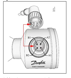

- B1: Red
- B2: Green
- A1: White
- A2: Black
Electrical check: Coil A and Coil B should measure 10 ohms at 20°C (68°F).
Controller Settings
To achieve the operational temperature and MOPD envelope, the controller must be set correctly:
- Total steps: 600 full steps.
- Step rate: 240 full steps/sec recommended.
- Phase current: 600mA RMS (800mA peak).
- Overdriving: The controller should have a function to overdrive the valve in the closing direction to compensate for lost steps.
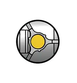
Moisture Indicator
For models with a sight glass, the moisture indicator changes color to show the state of the refrigerant:

- Green: Dry
- Yellow: Wet
Troubleshooting
If you encounter issues, check the following:
- No valve movement: Verify electrical connections, controller parameters (steps, phase current), and power supply.
- Internal leakage (Step Loss): Check for electrical noise, cable length, or accumulated backlash. Ensure the controller is configured to overdrive the valve.
- Insufficient capacity: Check if the valve is too small for the system, or if the evaporator is iced up.
- Flash gas: Check for lack of sub-cooling ahead of the expansion valve.
Manufacturer information
Danfoss A/S
Practical help
Common problems
No valve movement
Check electrical connections, verify controller parameters (steps, phase current, rotation direction), and ensure sufficient power supply.
Internal leakage (Step Loss)
Separate cable from high-power lines to reduce noise, check cable length, and ensure the controller is configured to overdrive the valve to compensate for lost steps.
Insufficient capacity
Verify system capacity against valve specifications, check superheat settings, and inspect for evaporator icing or foreign material blockage.
Flash gas
Check for lack of sub-cooling ahead of the expansion valve or verify if the valve is placed too high relative to the condenser outlet.
Before use
- Verify controller compatibility (must provide 800mA peak / 600mA RMS current per phase).
- Check cable length and wire diameter to minimize EMC interference.
- Ensure correct wiring of M12 connector (Coil A and Coil B).
- Confirm refrigerant compatibility.
- Configure controller with 600 full steps and 240 steps/sec rate.
Specs in practice
- Phase current
- 800mA peak / 600mA RMS required for optimal performance.
Images and diagrams
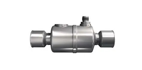
- Figure 1: Valve design showing stainless steel body, M12 connection, and sight glass.
- Figure 5: M12 connector pinout (B1, B2, A1, A2) and wire colors.
- Figure 8: Moisture indicator colors (Green=Dry, Yellow=Wet).
Model compatibility
- Compatible with Danfoss EKE 1A, EKE 1B, EKE 1C, MCX061V, MCX152V controllers.
- Third-party controllers must be configured with specific valve data (600 steps, 240 steps/sec rate).

Manual page author
Michael Turner
Technical manual editor
Reviews PDF manuals for structure, safety notes, and practical product details so readers can find the right information quickly.